High power light-emitting diode illuminating source heat radiating device

A technology of light-emitting diodes and heat-dissipating devices, which is applied to semiconductor devices of light-emitting elements, light sources, cooling/heating devices of lighting devices, etc. , High luminous efficiency and novel structure

Inactive Publication Date: 2008-09-10
SHANDONG GUANGYU LIGHTING TECH
View PDF0 Cites 14 Cited by
  • Summary
  • Abstract
  • Description
  • Claims
  • Application Information

AI Technical Summary

Problems solved by technology

At present, in order to meet the needs of lighting, semiconductor lighting fixtures, especially street lighting fixtures, must be assembled and packaged with multiple high-power chips to meet the design requirements. The temperature rise cannot be effectively suppressed, and the junction temperature will be quickly dissipated in the air, which will directly affect the service life and luminous efficiency of the LED, and even burn the LED
At present, most application manufacturers use a single 1W high-power chip to directly fix the light source on the heat dissipation lamp body when they have not solved the heat conduction solution. This method is easy to dissipate heat due to the low power, but the luminous intensity is not enough. , the effective range is insufficient, and it cannot be used as a light source for elevated street lights, but we also know that most of the electric energy of the light-emitting diodes in the prior art will be converted into heat energy. For LED devices packaged with multiple high-power chips, the large dissipation Power, large calorific value and high light output efficiency cannot be solved by the heat dissipation method and material of a single 1W LED device. If the heat generated by the high-power packaged LED cannot be effectively dissipated in the In the air, the temperature of the high-power integrated package LED chip is easy to be too high, resulting in a serious drop in luminous efficiency, or even burning the light-emitting diode
At present, when high-power light-emitting diodes are assembled and packaged for street lighting, the problem of heat dissipation cannot be solved, so it cannot be adopted and implemented.

Method used


Image

  • High power light-emitting diode illuminating source heat radiating device
  • High power light-emitting diode illuminating source heat radiating device
  • High power light-emitting diode illuminating source heat radiating device

Examples


Embodiment Construction

[0019] Below in conjunction with the accompanying drawings and specific examples for further description

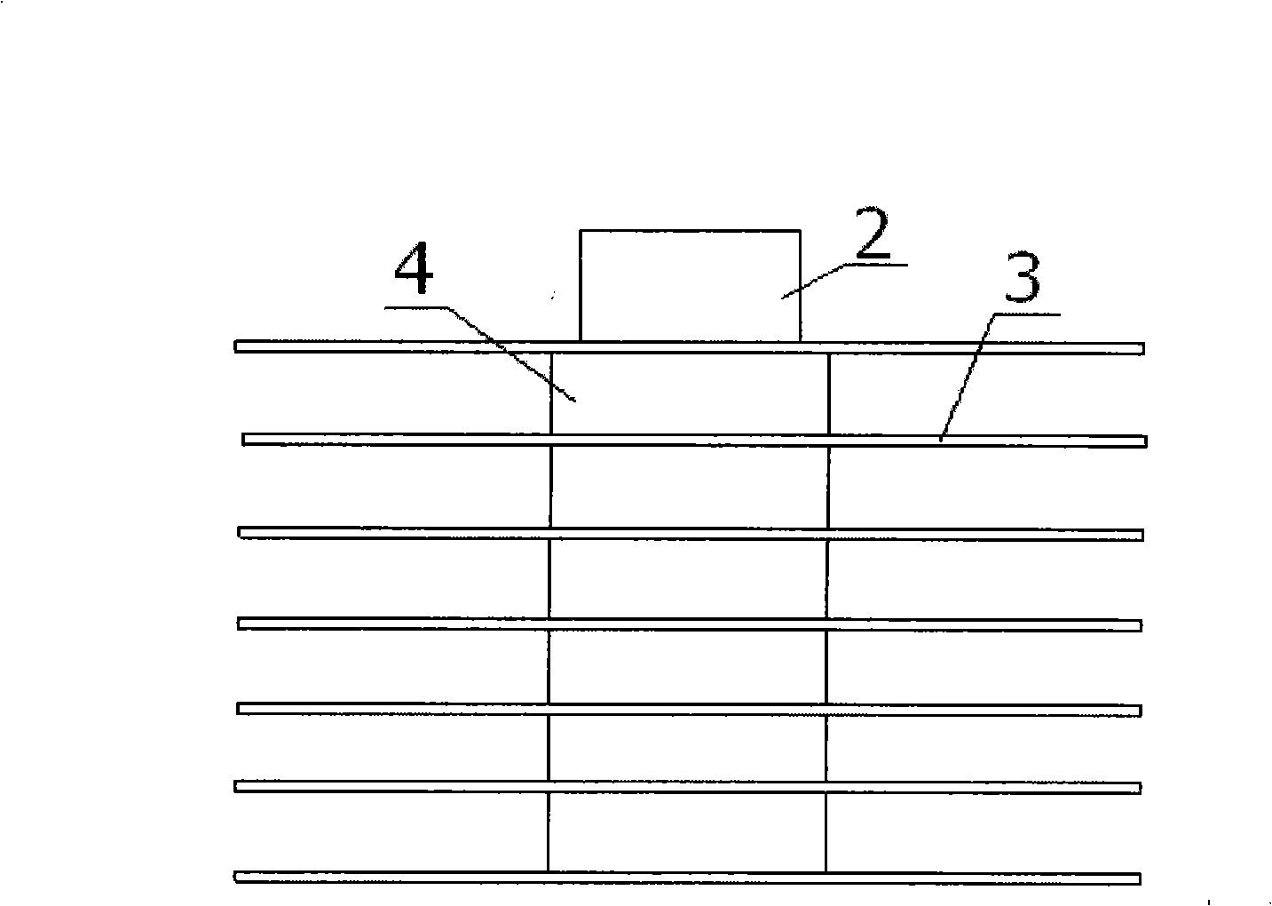
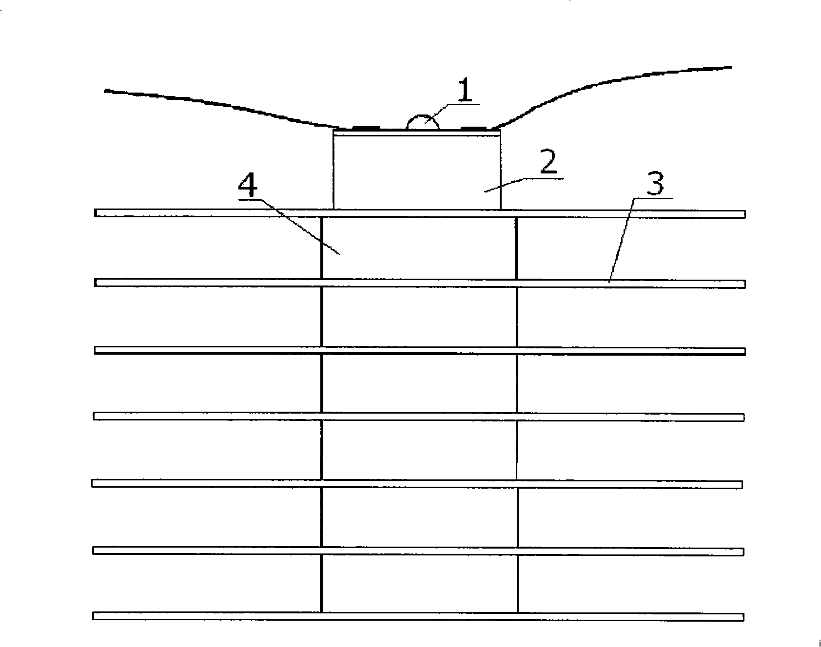
[0020] Such as figure 1 and 2 As shown, the heat conduction device of the high-power LED light source of the present invention includes a pure copper heat sink body 2 for installing a high-power LED light source 1 on the top, a pure aluminum heat sink 3 and a pure aluminum fastening ring 4; The aluminum heat sink 3 is fixed on the outer periphery of the pure copper heat conduction heat sink body 2 through the pure aluminum fastening ring 4 . The cooling fins 3 are fastened and embedded on the pure copper heat conduction heat sink body 2 through the hoop rings 4 in a manner of equidistant distribution.

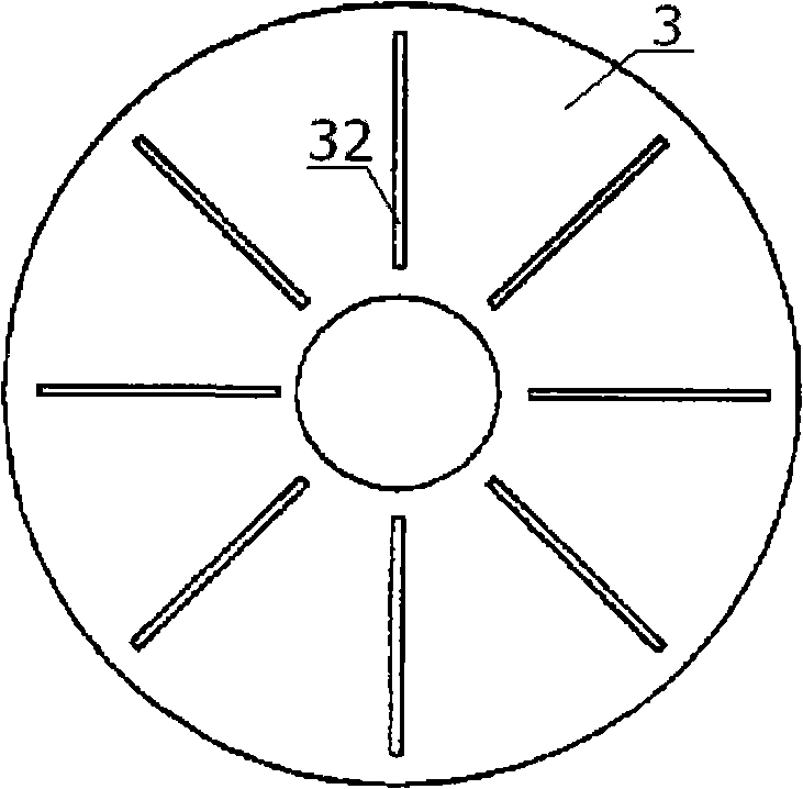
[0021] Certainly, in order to further improve heat dissipation efficiency, heat dissipation holes 31 or heat dissipation grooves 32 or heat dissipation holes 31 and heat dissipation grooves 32 may also be formed on the heat dissipation fin. The cross section of the pure...


PUM


Abstract

The invention relates to a conducting heat sink of an electric light source, in particular to a high power LED light source conducting heat sink. The high power LED heat sink provides a high power LED light source conducting heat sink with reasonable structure and good heat conduction and radiation. The high power LED light source conducting heat sink is used for a high power LED lighting device, and has the advantages of high efficiency and long service life.

Description

technical field [0001] The invention relates to a conduction and heat dissipation device for an electric light source, in particular to a heat conduction and heat dissipation device for a high-power LED light source. Secondary cooling device for high-power light-emitting diode light source in use Background technique [0002] We know that semiconductor lighting is one of the most promising high-tech fields in this century. As a new type of solid-state light source, semiconductor light source will become another leap in the history of human lighting after incandescent lamps and fluorescent lamps. At present, in order to meet the needs of lighting, semiconductor lighting fixtures, especially street lighting fixtures, must be assembled and packaged with multiple high-power chips to meet the design requirements. If the temperature rise cannot be effectively suppressed, the junction temperature will be quickly dissipated in the air, which will directly affect the service life a...

Claims


Application Information

Patent Timeline
Patent Type & Authority Applications(China)
IPC IPC(8): F21V29/00H01L23/36F21Y101/02F21V29/503F21V29/74F21V29/83F21V29/89F21Y115/10
Inventor 孙建国
Owner SHANDONG GUANGYU LIGHTING TECH
Why Eureka
Try Eureka