

Vertical bending layer energy converter cylinder stator and ultrasonic electromotor using this stator
A transducer and cylinder technology, applied in the direction of piezoelectric effect/electrostrictive or magnetostrictive motors, generators/motors, electrical components, etc., can solve the constraints of mechanical output capacity and the distortion of the particle vibration track on the surface of the stator , Reduce the mechanical output capability and controllability of ultrasonic motors, and achieve the effects of avoiding inconsistent vibration, improving mechanical output capability and controllability, and improving performance
- Summary
- Abstract
- Description
- Claims
- Application Information
AI Technical Summary
Problems solved by technology
Method used
Image

Examples
specific Embodiment approach 1
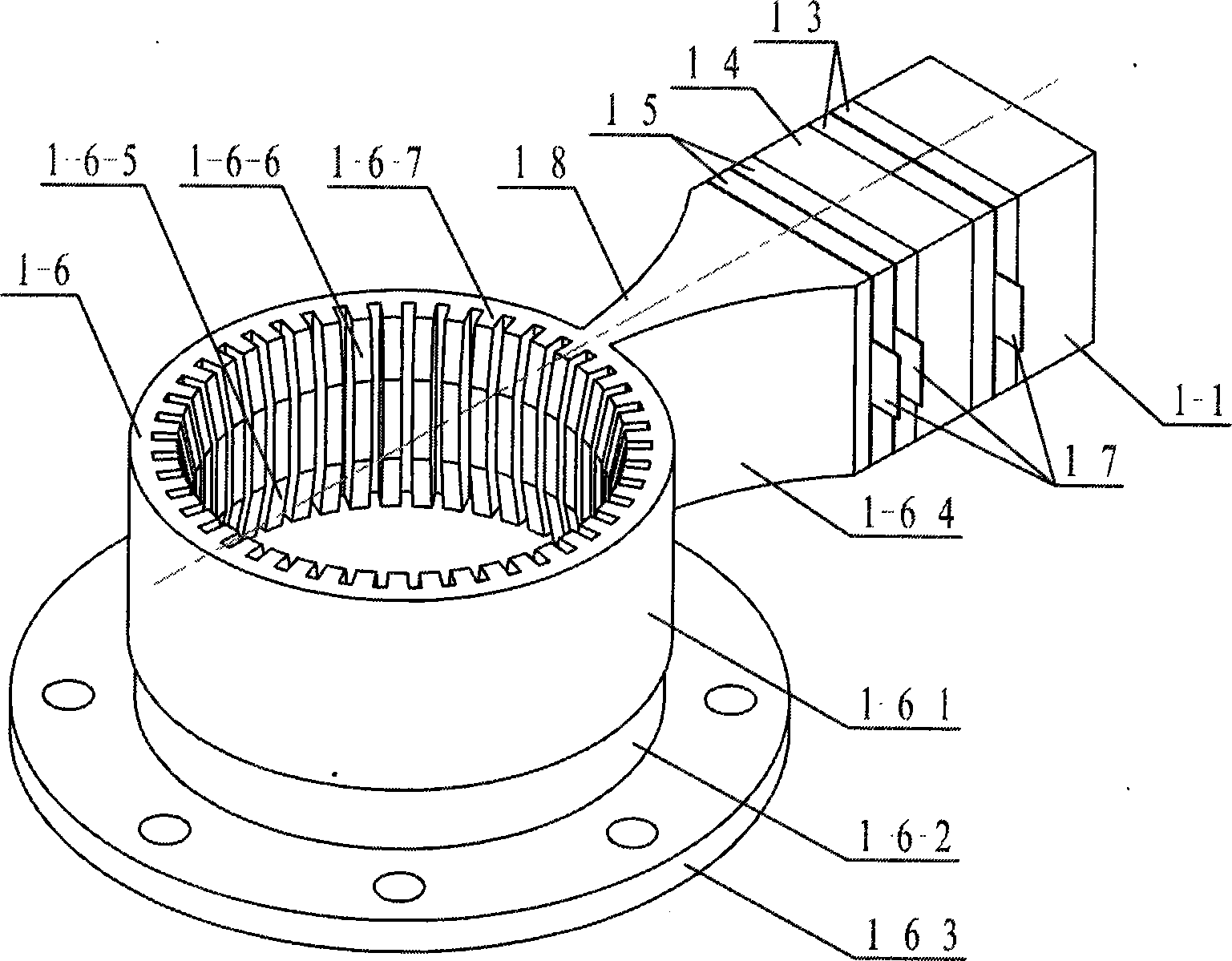
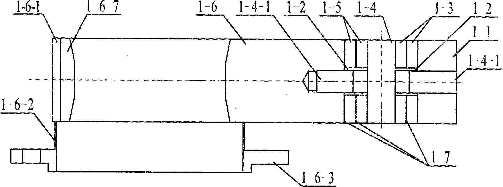
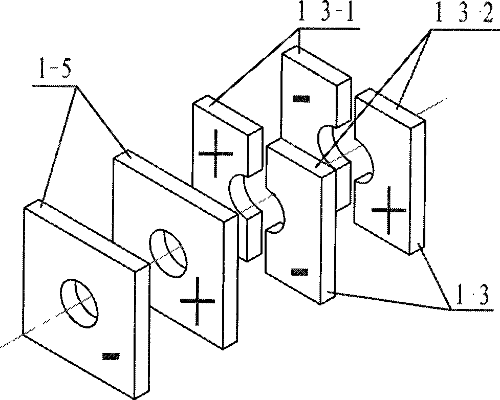
[0010] Specific implementation mode one: combine Figure 1 to Figure 3 To illustrate this embodiment, the longitudinal bending sandwich transducer type cylindrical stator described in this embodiment includes a driving cylinder 1-6 and a longitudinal bending sandwich transducer 1-8, and the driving cylinder 1-6 includes a cylinder 1- 6-1, the thin-walled ring 1-6-2 and the cylindrical flange 1-6-3, the thin-walled ring 1-6-2 is between the cylinder 1-6-1 and the cylindrical flange 1-6-3, so The cylinder 1-6-1, the thin-walled ring 1-6-2 and the cylinder flange 1-6-3 are coaxial; the longitudinal bending sandwich transducer 1-8 includes a front end cover 1-6-4 and a rear end cover 1 -1, insulating sleeve 1-2, a pair of bending vibration piezoelectric ceramic sheets 1-3, flanges 1-4, a pair of longitudinal vibration piezoelectric ceramic sheets 1-5 and three electrode sheets 1-7, the front end The cover 1-6-4 is a quadrangular prism with a rectangular cross-section and tapering...
specific Embodiment approach 2
[0016]Embodiment 2: The difference between this embodiment and the longitudinally curved sandwich transducer-type cylinder stator described in Embodiment 1 is that the inner side of the cylinder 1-6-1 is evenly distributed with the cylinder 1 -6-1 Comb-shaped drive teeth 1-6-7 parallel to the central axis, the comb-shaped drive teeth 1-6-7 are symmetrical up and down with an upper end cone surface 1-6-6 and a lower end cone surface 1-6-5 .
[0017] Comb-shaped drive teeth 1-6-7 are added in the cylinder 1-6-1 of this embodiment, which can amplify the amplitude of the particle vibration track on the surface of the stator.
[0018] The comb-shaped driving teeth 1-6-7 described in this embodiment are vertically symmetrical with an upper tapered surface 1-6-6 and a lower tapered surface 1-6-5, which can increase the contact area between the stator and the rotor and improve the output. moment.
specific Embodiment approach 3
[0019] Embodiment 3: The difference between this embodiment and the longitudinally curved sandwich transducer-type cylindrical stator described in Embodiment 1 or 2 is that the front end cover 1-6-4 and the driving cylinder 1-6 adopt a The whole piece of metal material is processed into one piece of cylinder / front cover.
[0020] In this embodiment, the front end cover 1-6-4 and the driving cylinder 1-6 are integrally structured to reduce energy loss and help to improve the controllability of the particle vibration track on the surface of the comb-shaped driving teeth 1-6-7 , so that the operation of the longitudinal bending sandwich transducer type cylindrical stator described in this embodiment is more stable and reliable.
PUM
 Abstract
Description
Claims
Application Information