
Centrifugal separator disk plate

A technology of centrifugal separation and discs, which is applied in centrifuges and other directions, can solve the problems of affecting the separation process and the large influence of dispersed phase flow, and achieve the effects of improving separation efficiency, increasing production capacity, and shortening time

Active Publication Date: 2008-09-17
溧阳常大技术转移中心有限公司
View PDF2 Cites 15 Cited by
  • Summary
  • Abstract
  • Description
  • Claims
  • Application Information

AI Technical Summary

Problems solved by technology

Due to the small distance between the discs (0.3-3mm), the flow of the continuous phase has a great influence on the flow of the dispersed phase, thereby affecting the separation process

Method used


Image

  • Centrifugal separator disk plate
  • Centrifugal separator disk plate
  • Centrifugal separator disk plate

Examples


Embodiment Construction

[0018] Embodiments of the present invention will be described below in conjunction with the accompanying drawings.

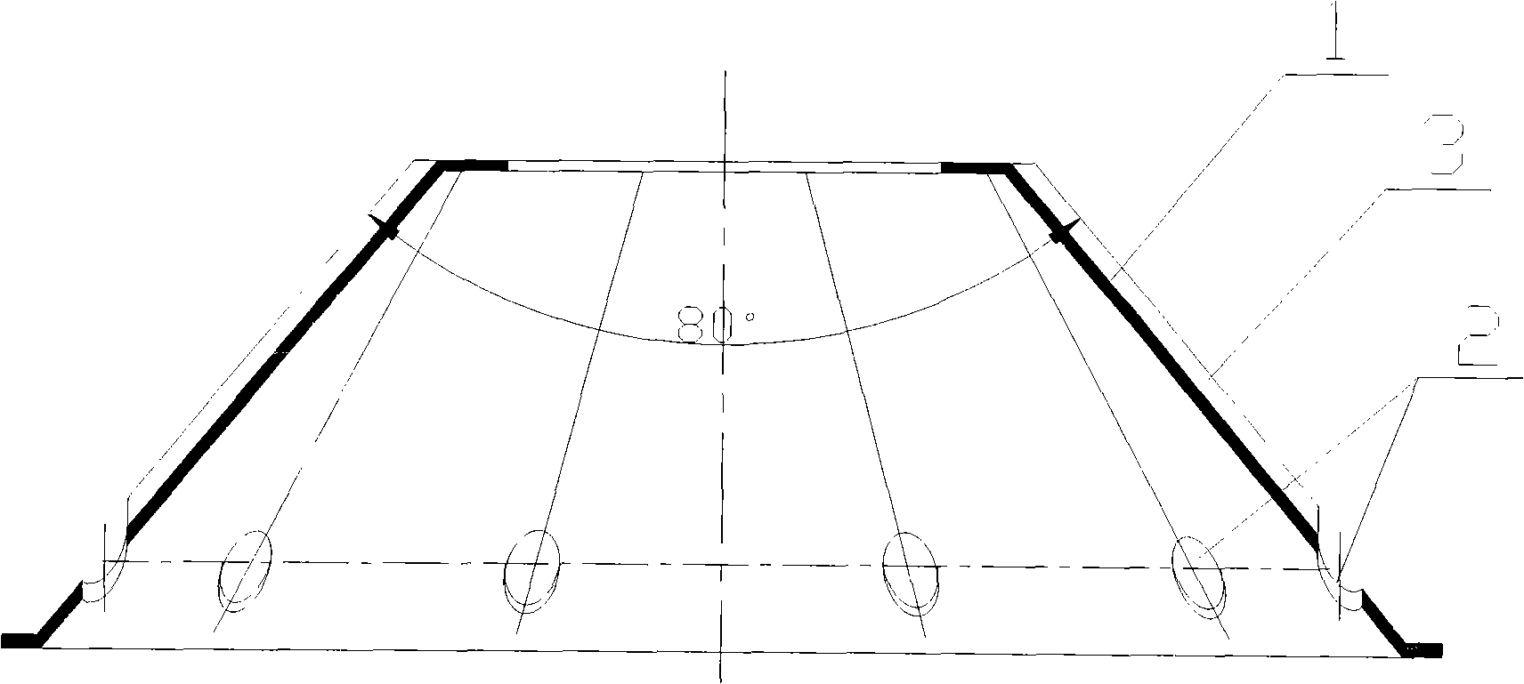
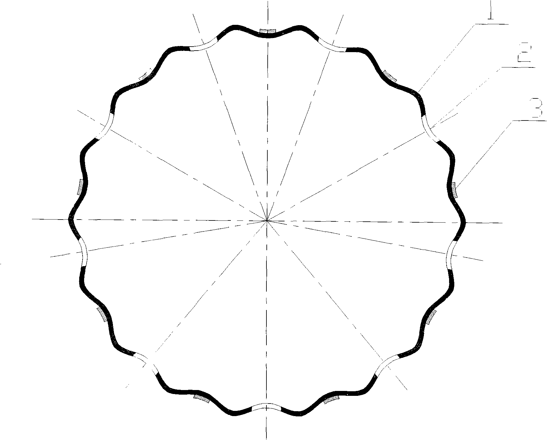
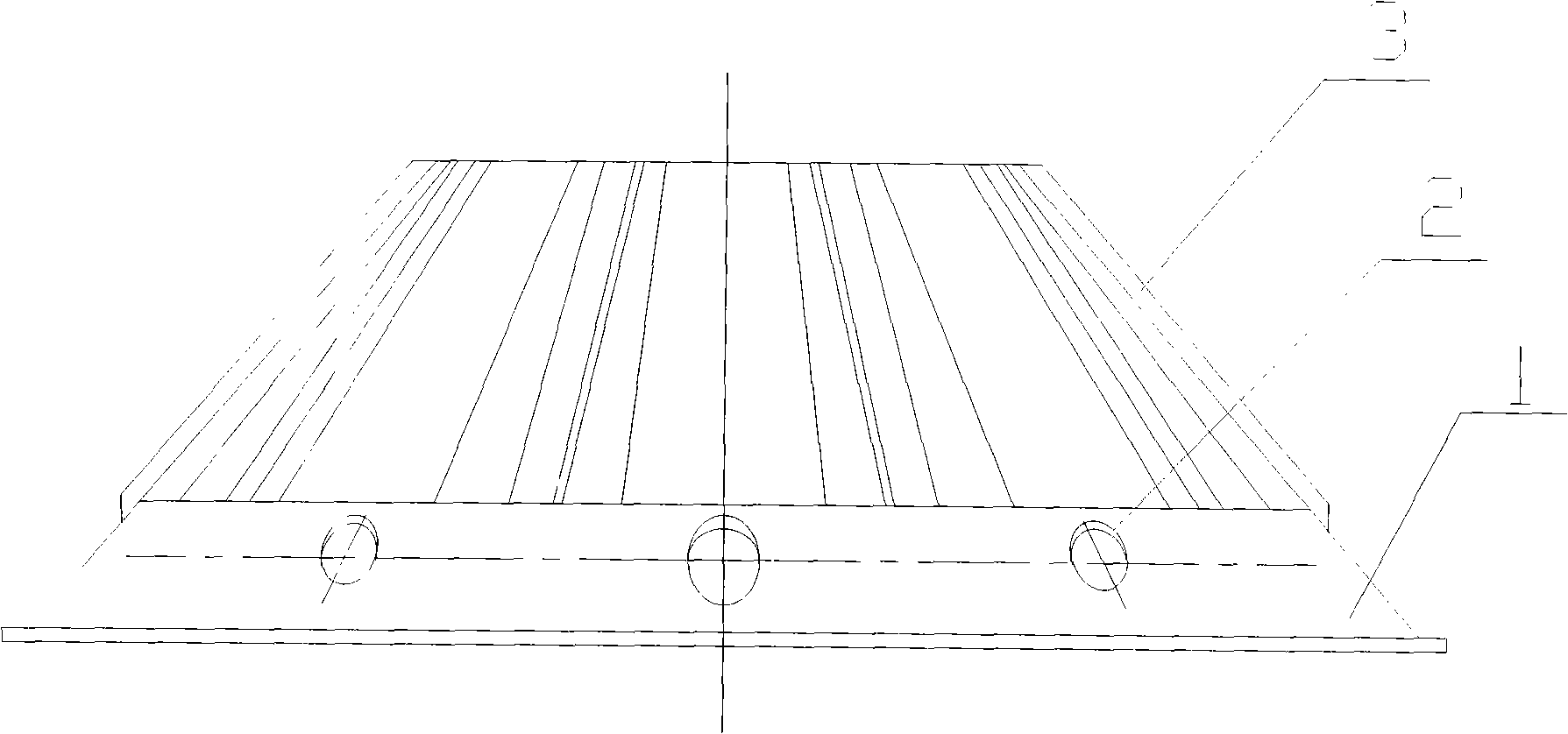
[0019] The disc composition of the centrifuge that present embodiment provides is as follows figure 1 , figure 2 and image 3 shown. The disc includes a disc body (1), several feeding holes (2) and several ribs (3), wherein the disc body is corrugated along the circumferential direction and straight or helical along the height direction, but No corrugation is set in the area from the big end face to the diameter of the inner big end of the conical disc that is 0.1 times from the big end face. A feeding hole (2) or a rib (3) is arranged in the inner recess of the disc. The feeding holes (2) and ribs (3) are alternately arranged in the circumferential direction.

[0020] Wherein the full cone angle of the corrugated conical disc is 80°.

[0021] The corrugation of the corrugated conical disc is sinusoidal, the number of waves is 16-32, and the amplitude is ...


PUM

PropertyMeasurementUnit
Heightaaaaaaaaaa

Abstract

The invention relates to discs of a disc type centrifugal separation machine, comprising a disc body, a feeding hole and a rib, wherein the disc body is a ripple shape along the circumferential direction, and a straight line or helical line along the height direction, the feeding hole or the rib is arranged at the curved position of the disc. The feeding hole and the rib are arranged in interval along the circumference direction. The discs are coaxially overlapped, and the space is determined by the height of the rib. The space formed between the discs is also a ripple shape. The ripple shaped space recessed towards the axis side of the taper disc is a light phase channel, and the ripple shaped space projecting outwards is a heavy phase channel. The invention has the advantages that the ripple shaped taper disc respectively provides the dispersion phase and the continuous phase with flow channels, so that the mutual influence of two-phase flow is reduced, and the separation efficiency of the disc type centrifugal separation machine can be improved.

Description

technical field [0001] The invention relates to the field of centrifugal separators, in particular to discs of centrifugal separators. Background technique [0002] The disc is the main part of the disc centrifuge, forming a settling space or channel between the discs. Its main function is (1) according to the "shallow pool principle", to reduce the particle settlement distance, (2) using the cone shape to self-clean the settlement surface, that is, the sediment on the settlement surface moves away by itself under the action of centrifugal force. The flow of continuous phase and dispersed phase between the discs is mainly countercurrent. The existing discs are all simple conical surfaces, such as US2007 / 0270298A1, US2007 / 0066476A1, US2004 / 0023783A1, ZL89107941, ZL88107069, and so on. Due to the small distance between the discs (0.3-3mm), the flow of the continuous phase has a great influence on the flow of the dispersed phase, thereby affecting the separation process. Co...

Claims


Application Information

Patent Timeline
IPC IPC(8): B04B7/00B04B7/08
CPCB04B7/14
Inventor 袁惠新
Owner 溧阳常大技术转移中心有限公司
Features
  • Generate Ideas
  • Intellectual Property
  • Life Sciences
  • Materials
  • Tech Scout
  • Unparalleled Data Quality
  • Higher Quality Content
  • 60% Fewer Hallucinations
Learn More