Thrust bearing applying interface sliding technology

A thrust bearing and sliding technology, applied in the field of thrust bearings, can solve the problems of complex structure and size, and achieve the effects of low manufacturing cost, small size, simple and compact structure

Inactive Publication Date: 2008-09-17
HUAIHAI INST OF TECH
View PDF0 Cites 37 Cited by
  • Summary
  • Abstract
  • Description
  • Claims
  • Application Information

AI Technical Summary

Problems solved by technology

It limits the application of hydrodynamic lubricated bear...

Method used


Image

  • Thrust bearing applying interface sliding technology
  • Thrust bearing applying interface sliding technology
  • Thrust bearing applying interface sliding technology

Examples


Embodiment 1

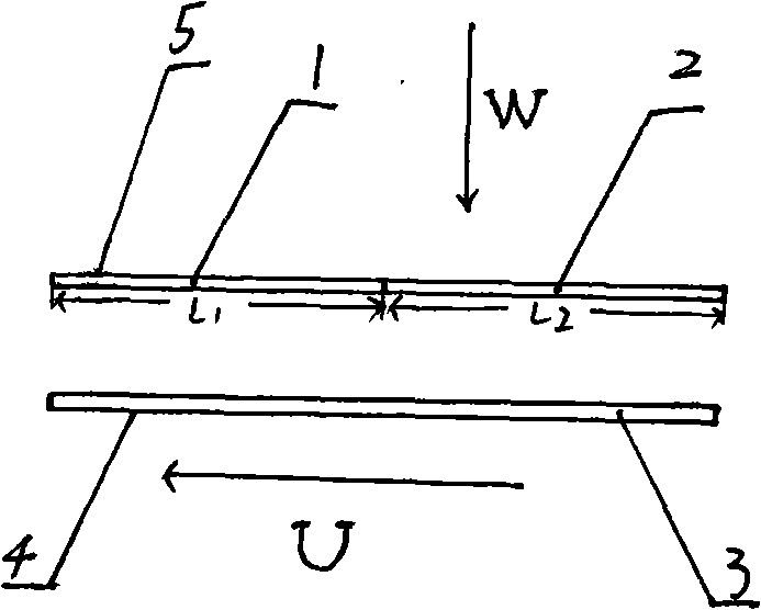
[0036] Example 1. refer to figure 1 . A thrust bearing using interface sliding technology, which includes a stationary plate 5 and a moving plate 4 parallel to each other, the gap between the stationary plate 5 and the moving plate 4 is filled with fluid lubricating oil, and the part of the stationary plate 5 The lower surface is provided with II coating 2, the remaining lower surface is provided with I coating 1, and the upper surface of the moving flat plate 4 is provided with III coating 3, so that a certain relative movement between the stationary flat plate 5 and the moving flat plate 4 Just make these two flat plates form a thrust bearing; the I coating 1 is a fluorocarbon coating; the II coating 2 and III coating 3 are mica powder coatings modified by a silane coupling agent.

Embodiment 2

[0037] Example 2. In the thrust bearing described in Example 1, the II coating 2 or III coating 3 is prepared by the following method: adding a silane coupling agent into an organic solvent to form a solution with a concentration of 0.1%, and using the silane coupling agent Add the mica powder into the solution at a ratio of 1:100 by weight of the coupling agent to the mica powder, mix evenly, apply the mixture on the surface of the static plate 5 or the moving plate 4, and form a coating after air-drying.

Embodiment 3

[0038] Example 3. In the thrust bearing described in Example 1, the II coating 2 or III coating 3 is prepared by the following method: adding a silane coupling agent into an organic solvent to form a solution with a concentration of 0.3%, and using the silane coupling agent Add the mica powder into the solution at a ratio of 2:100 by weight of the joint agent and the mica powder, mix evenly, apply the mixture on the surface of the static plate 5 or the moving plate 4, and form a coating after air-drying.


PUM

PropertyMeasurementUnit
Thicknessaaaaaaaaaa
Thicknessaaaaaaaaaa
Thicknessaaaaaaaaaa

Abstract

The invention is a thrust bearing using the interface slippage technology, and is characterized in that the bearing comprises a static and a moving flat panels that are parallel to each other; the gap between the static and the moving flat panels is filled with fluid lubricating oil; a coating layer II is arranged on part of the static flat panel; a coating layer I is arranged on the rest partof the static flat panel; a coating layer III is arranged on the surface of the moving flat panel, Therefore, a thrust bearing is formed by the two flat panels through a certain relative moving between the static flat panel and the moving flat panel, the coating layer I is a fluorocarbon coating layer, and the coating layer II and III are coatings of mica powder modified by silane coupling agents. The thrust bearing is simple in the bearing forming and has a certain carrying capacity, good anti-friction and wear-resistance without the need of processing the matching surface into a geometric shape. With simple and compact structure and small size and low production cost, the thrust bearing can replace the traditional fluid motive power lubrication thrust bearing for bearing purpose.

Description

technical field [0001] The invention relates to a bearing, in particular to a thrust bearing using interface sliding technology. Background technique [0002] Bearings are important mechanical components used to support shaft parts. Bearings are divided into sliding bearings and rolling bearings. There are the following main performance requirements for bearings: support accuracy, support rigidity, low friction coefficient and wear resistance. This requires the bearing to be a very precise mechanical part, and also requires it to have a large enough load-carrying capacity. In order to achieve good anti-friction and wear resistance, the bearing also needs to have good lubrication performance. So far, although the bearing technology is relatively mature, it is all based on the traditional lubrication theory. At present, rolling bearings and sliding bearings are used in different occasions and each has its own advantages. Since the present invention relates to sliding bear...

Claims


Application Information

Patent Timeline
IPC IPC(8): F16C17/08F16C33/04
Inventor 张永斌袁虹娣
Owner HUAIHAI INST OF TECH
Why Eureka
Try Eureka