
Position detector

A detector and target detection technology, applied in the direction of electric/magnetic position measurement, instruments, measuring devices, etc., can solve the problems of high-speed performance limitations, achieve high precision and speed, high speed, and improve the effect of interpolation accuracy

Active Publication Date: 2008-09-17
OKUMA CORP
View PDF4 Cites 12 Cited by
  • Summary
  • Abstract
  • Description
  • Claims
  • Application Information

AI Technical Summary

Problems solved by technology

Thus, a rotating shaft driven by a motor direct drive scheme that facilitates high-speed rotation is limited in high-speed performance by existing position detectors

Method used


Image

  • Position detector
  • Position detector
  • Position detector

Examples


Embodiment Construction

[0013] Embodiments of the present invention will be described below with reference to the drawings.

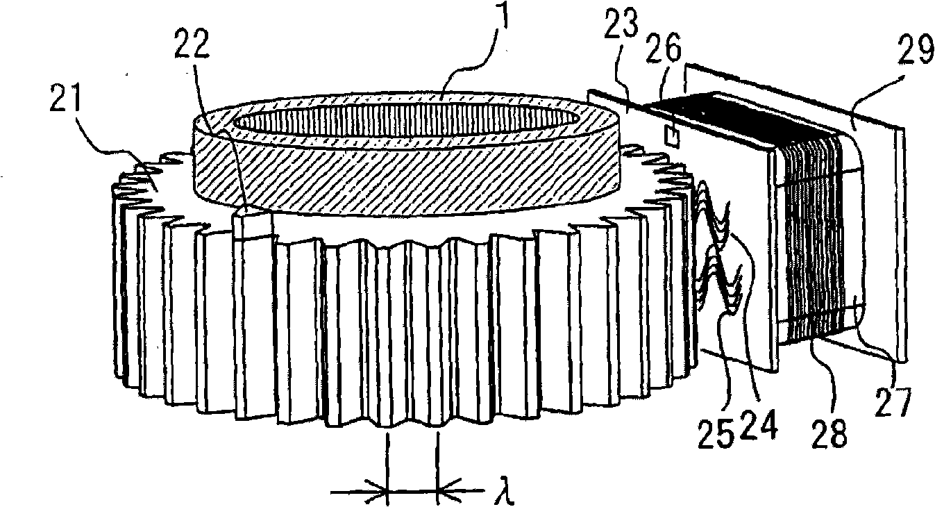
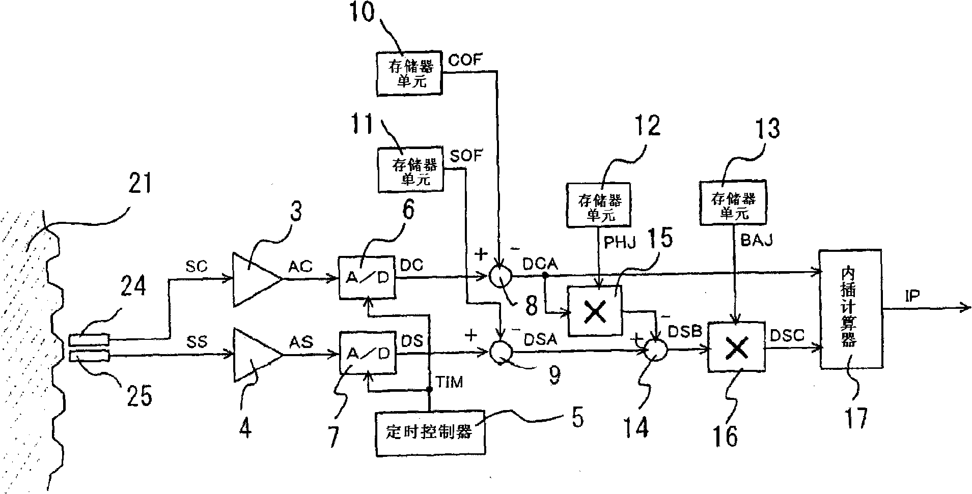
[0014] figure 2 is a diagram showing the basic structure of a position detector. image 3 to show figure 2 A block diagram of the interpolation operation of the signal processing circuit 29 in . exist figure 2 Among them, the rotor 21 fixed on the rotating shaft 1 is composed of a magnetic member having 36 depressions and protrusions on its outer circumference at a pitch of wavelength λ=10 degrees in one rotation. On one of the 36 protrusions of the rotor 21, a protrusion 22 made of a magnetic member for indicating the start is attached. The printed circuit board 23 mounted on the non-rotating portion of the measurement target (motor) is located on the side adjacent to the outer surface of the rotor 21 . Formed on the printed circuit board 23 are two kinds of detection coils 24 and 25 forming a sinusoidal conductive pattern, and a detection coil 26 for detecting a prot...


PUM


Abstract

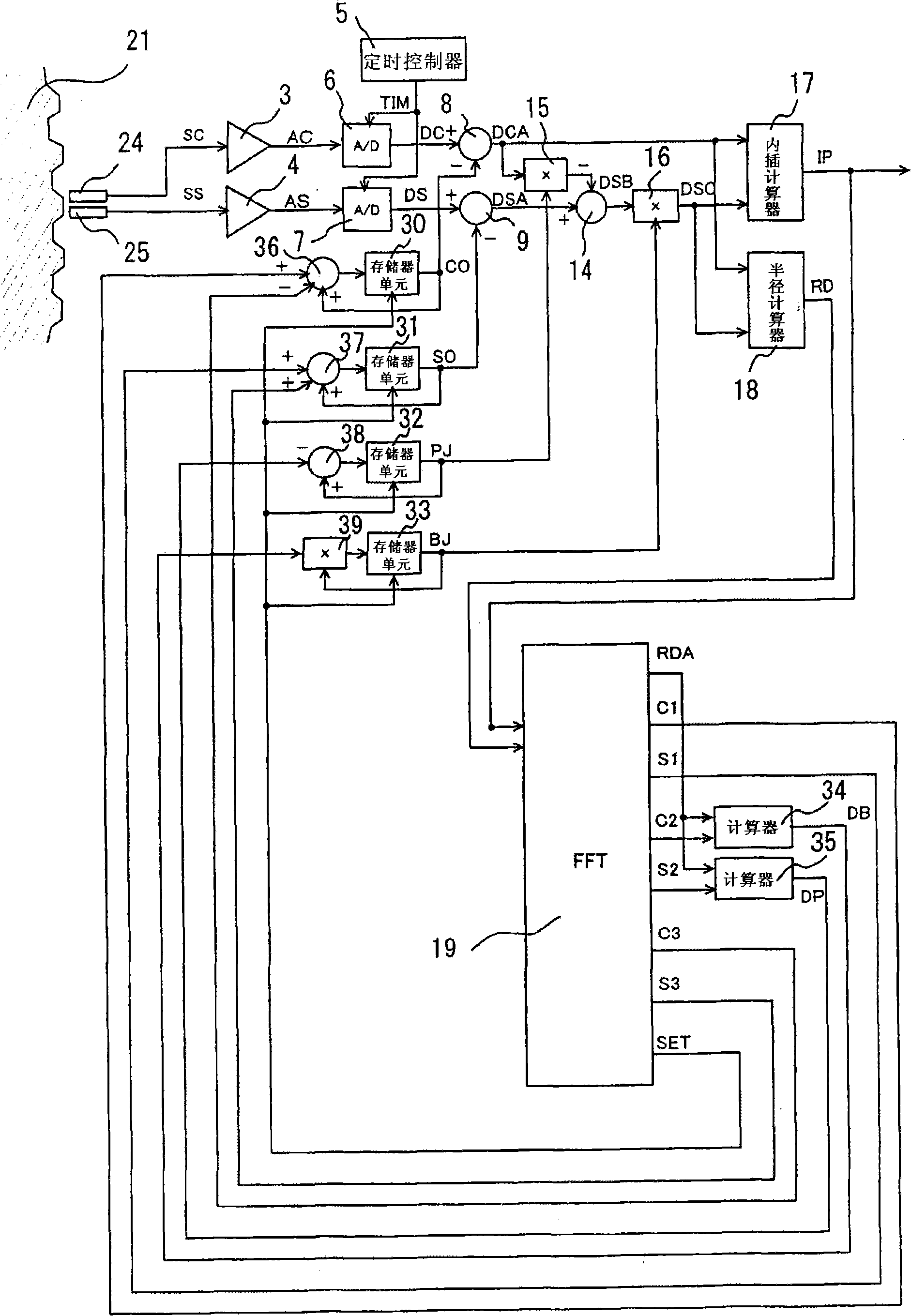
The invention relates to a position detector for detecting object displacement. Two position sensors provide, as outputs, two signals that vary sinusoidally at a pitch of wavelength lambda with respect to a displacement of a target and have phases shifted from each other by 90 DEG . A memory unit has stored therein offset values for the two signals, and two subtractors eliminate the offset values from the two signals, respectively. The two signals after offset elimination are converted into position data in an interpolation calculator. A radius calculator calculates a radius value of the two signals after offset elimination. An FFT calculates offset values based on the position data and the radius values, and the calculated offset values are used to update the values stored in the memory unit. An amplitude ratio correction value and a phase difference correction value for the two signals are updated similarly. By performing elimination of the components that degrade interpolation accuracy at every rotational position, interpolation accuracy is improved.

Description

[0001] priority information [0002] This application claims priority from Japanese Patent Application No. 2007-068620 filed on March 16, 2007, which is hereby incorporated by reference in its entirety. technical field [0003] The invention relates to a position detector which converts into position information an output signal from a position sensor which outputs two signals which vary sinusoidally at a distance of wavelength λ with respect to a measured displacement and which have Phases switched at 90 degrees to each other. Background technique [0004] At the rotating shaft of the machine tool's turntable or the like, the previously adopted transmission scheme is accomplished by combining a reduction gear such as a worm gear with a servo motor. Disadvantages of transmission schemes using reduction gears are, however, that precision decreases due to backlash and that the increase in rotational speed is limited. Therefore, in recent years, an electric motor direct drive...

Claims


Application Information

Patent Timeline
Patent Type & Authority Applications(China)
IPC IPC(8): G01D5/244
CPCG01D5/24409G01D5/24452G01D5/2448G01D5/2449G01D5/2451G01D18/001G01B7/003G01B21/045G01D5/245
Inventor 林康一
Owner OKUMA CORP
Learn More