

Method for regulating high power laser apparatus light path alignment
A laser device and optical path collimation technology, applied in optics, optical components, instruments, etc., can solve the problems of inconvenient spatial filter arrangement, increase the length of the main optical path, etc., and achieve the effects of easy adjustment, simple equipment and high precision
- Summary
- Abstract
- Description
- Claims
- Application Information
AI Technical Summary
Problems solved by technology
Method used
Image

Examples
Embodiment Construction
[0017] The present invention will be further described below in conjunction with the embodiments and accompanying drawings.
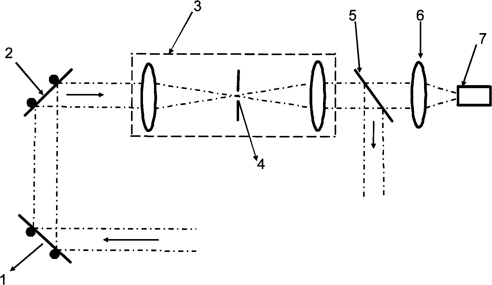
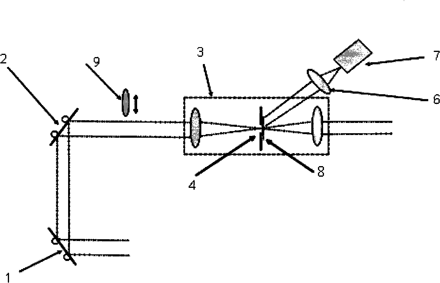
[0018] see figure 2 , figure 2 A schematic diagram of the far-field detection optical path of the present invention, and a method for adjusting the alignment of the optical path of a high-power laser device in the present invention includes the following steps:
[0019] 1. A transmission grating 8 is placed close to the small hole plate behind the small hole plate of the spatial filter 3, and the size of the transmission grating 8 is larger than the small hole 4 of the spatial filter 3;
[0020] 2. Start the laser light source, and insert a negative lens 9 in the main optical path between the second reflector 2 and the spatial filter 3, so that the laser beam is filled with the small hole 4; the outline of the small hole 4 is passed through the transmission grating 8 After the diffraction, it is imaged on the far-field detector 7 through the imaging...
PUM
 Abstract
Description
Claims
Application Information