
Electromotor

A motor and rotary drive technology, applied in the field of motors, can solve the problems of high heat generation of the motor 105, difficulty in suppressing the accumulation of heat in the motor 105, difficulty in dissipating heat, etc., and achieve the effect of improving heat dissipation characteristics

Inactive Publication Date: 2008-09-17
PANASONIC CORP
View PDF1 Cites 11 Cited by
  • Summary
  • Abstract
  • Description
  • Claims
  • Application Information

AI Technical Summary

Problems solved by technology

Therefore, it is difficult to dissipate the heat generated by the stator 100, and it is difficult to suppress the accumulation of heat in the motor 105.
Therefore, when the electric motor 105 is further driven with a high torque, the heat generation of the electric motor 105 becomes a particularly large problem.

Method used


Image

  • Electromotor
  • Electromotor
  • Electromotor

Examples


Embodiment Construction

[0032] Embodiments of the present invention will be described below based on the drawings. In addition, the following description is an embodiment example of the present invention, and does not limit the content of the present invention.

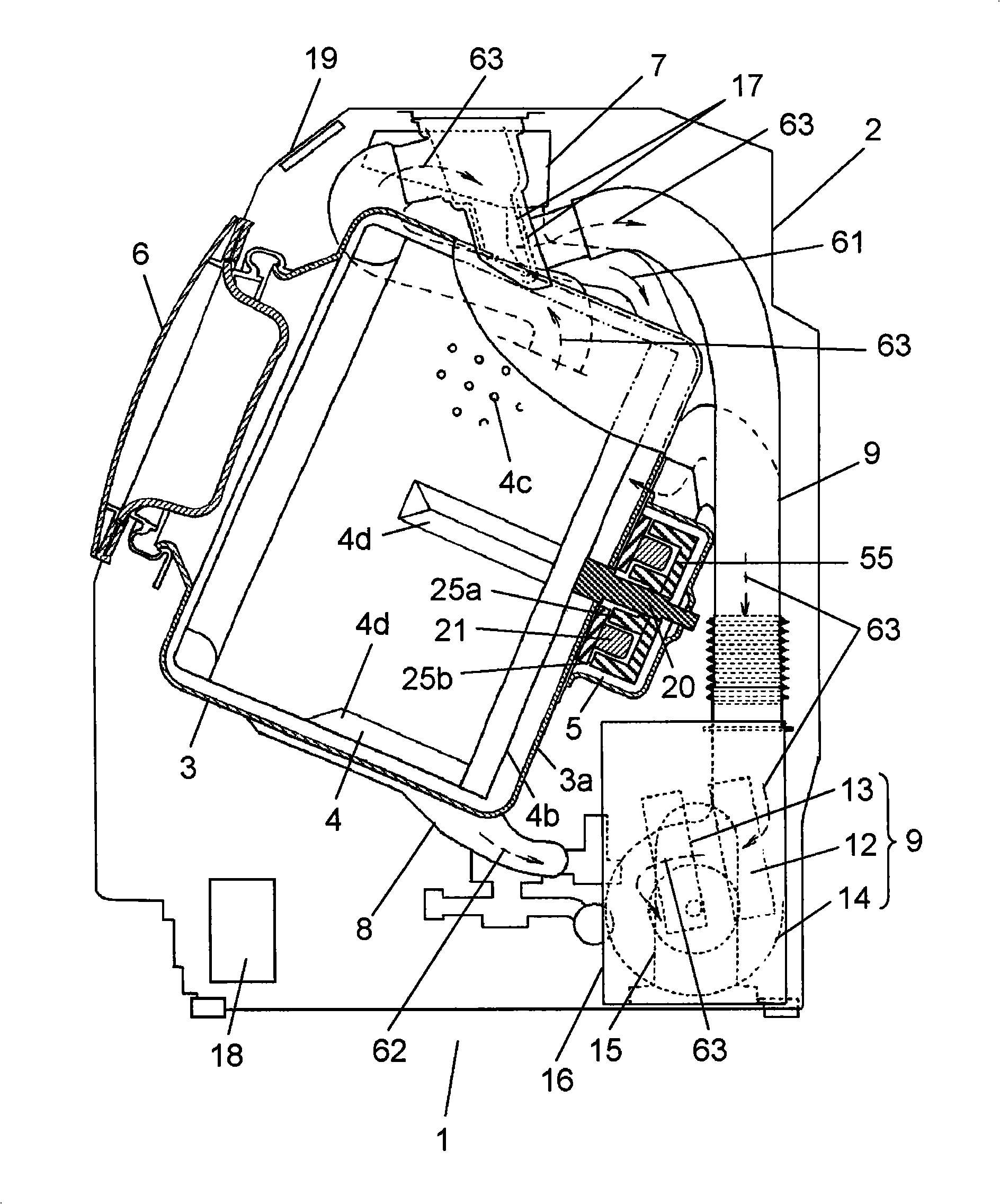
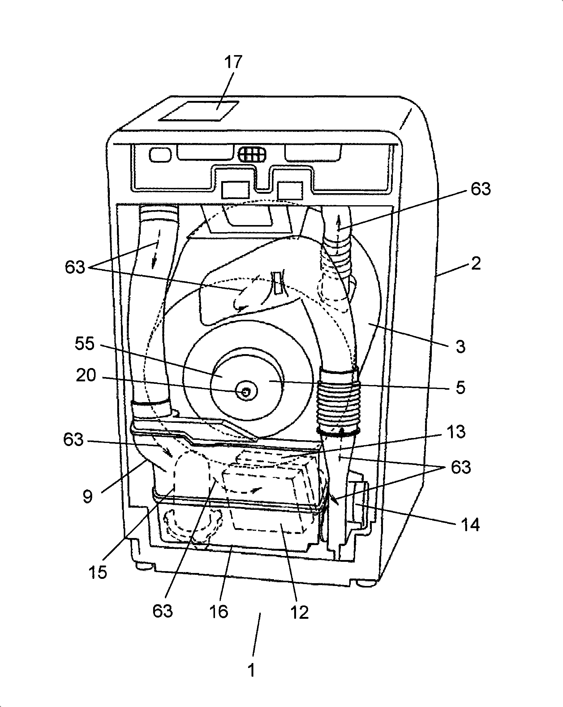
[0033] use figure 1 and figure 2 The structure and operation of front-loading washing machine 1 (hereinafter referred to as washing machine 1 ) having electric motor 5 according to the embodiment of the present invention will be described. in addition, figure 1 It is a cross-sectional view of washing machine 1 using motor 5 according to the embodiment of the present invention. figure 2 for observation figure 1 A rear view of the interior of the washing machine 1 is shown.

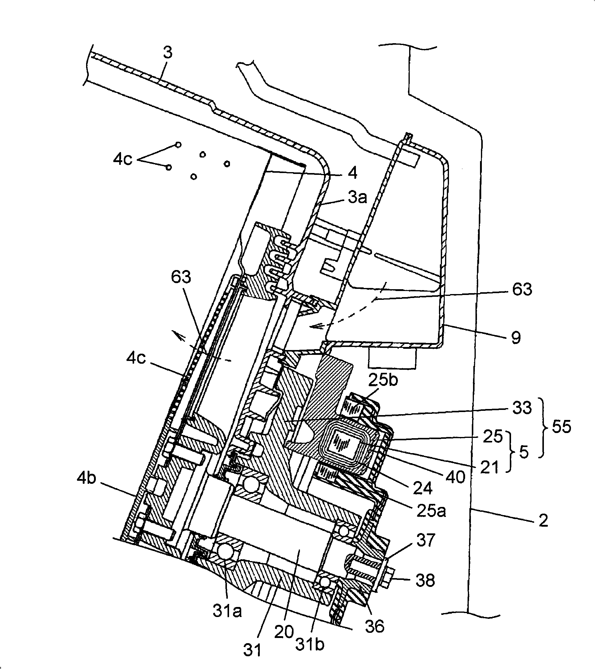
[0034] like figure 1 As shown, the washing machine 1 of the present embodiment is provided with a water tank 3 and a rotary drum 4 (hereinafter referred to as the drum 4 ) in the washing machine casing 2 (hereinafter referred to as the casing 2 ). The water t...


PUM


Abstract

The invention provides an electric motor. The electric motor (5) has rotor (25) and stator (21); the stator (21) has winding (24), stator resin mould (22) and concave-convex part (40); the stator resin mould (22) is formed by molding the winding (24) by the resin material; the concave-convex part (40) has recess (40a) and stator projection (40b) arranged on the end face (22a) of the stator resin mould (22); the recess (40a) is arranged on the end face (22a) extending from the winding (24) along the axial direction. Through the construction, the invention provides an electric motor (5) for improving the heat-radiating property radiating from the stator (21).

Description

technical field [0001] The present invention relates to a motor having a stator attached to a fixed portion of a washing machine or the like, and a rotor attached to a rotating shaft of the washing machine or the like. Background technique [0002] For example, in Figure 12 , Figure 13 Conventional front-loading washing machine 100 as shown (hereinafter referred to as washing machine 100 ) and the like use conventional motor 105 having stator 110 and rotor 111 . [0003] The washing machine 100 is provided with a water tank 102 and a rotary drum 104 (hereinafter referred to as the drum 104 ) in a washing machine main body 101 (hereinafter referred to as the main body 101 ). The tank 102 is elastically supported on the main body 101 by a suspension structure (not shown). The drum 104 is disposed in the water tank 102, and a plurality of holes 103 are formed therein. In addition, the drum 104 is driven to rotate by the motor 105 . A freely openable door 106 is provided o...

Claims


Application Information

Patent Timeline
Patent Type & Authority Applications(China)
IPC IPC(8): H02K3/30H02K3/32H02K1/12H02K1/22D06F37/30
CPCH02K1/18D06F37/40D06F37/304H02K9/22H02K1/14
Inventor 桧胁英治井上弘之
Owner PANASONIC CORP
Learn More