
Engine ventilating device

A ventilation device and engine technology, which is applied to engine components, machines/engines, mechanical equipment, etc., can solve the problems of easily polluted engine air, high oil consumption, and engine oil burning, etc., to achieve good results, prevent air pollution, and prevent The effect of burning oil

Inactive Publication Date: 2008-09-24
WUXI KIPOR POWER CO LTD
View PDF0 Cites 9 Cited by
  • Summary
  • Abstract
  • Description
  • Claims
  • Application Information

AI Technical Summary

Problems solved by technology

[0002] In the prior art, the ventilation device of the crankcase of the engine is relatively simple. Usually, a steel wire filter screen is installed on the oil filler cap cover, and some small holes communicate with the atmosphere, and some have a small hole at the highest point of the cylinder cover. The rubber tube communicates with the outside world, so that the oil mist gas in the crankcase can directly communicate with the atmosphere, but this structure is easy to pollute the air around the engine, and oil droplets will form sludge on the ground
In addition, there is also a rubber diaphragm valve installed at the highest point in the cylinder head cover to allow the outlet gas to flow into the intake pipe, and the oil gas contains more oil particles, which burn after entering the cylinder, which will easily cause the engine to burn oil, high oil consumption, Blue smoke from the exhaust, resulting in carbon deposit failures in cylinders, pistons, piston rings, fuel injectors and valves

Method used

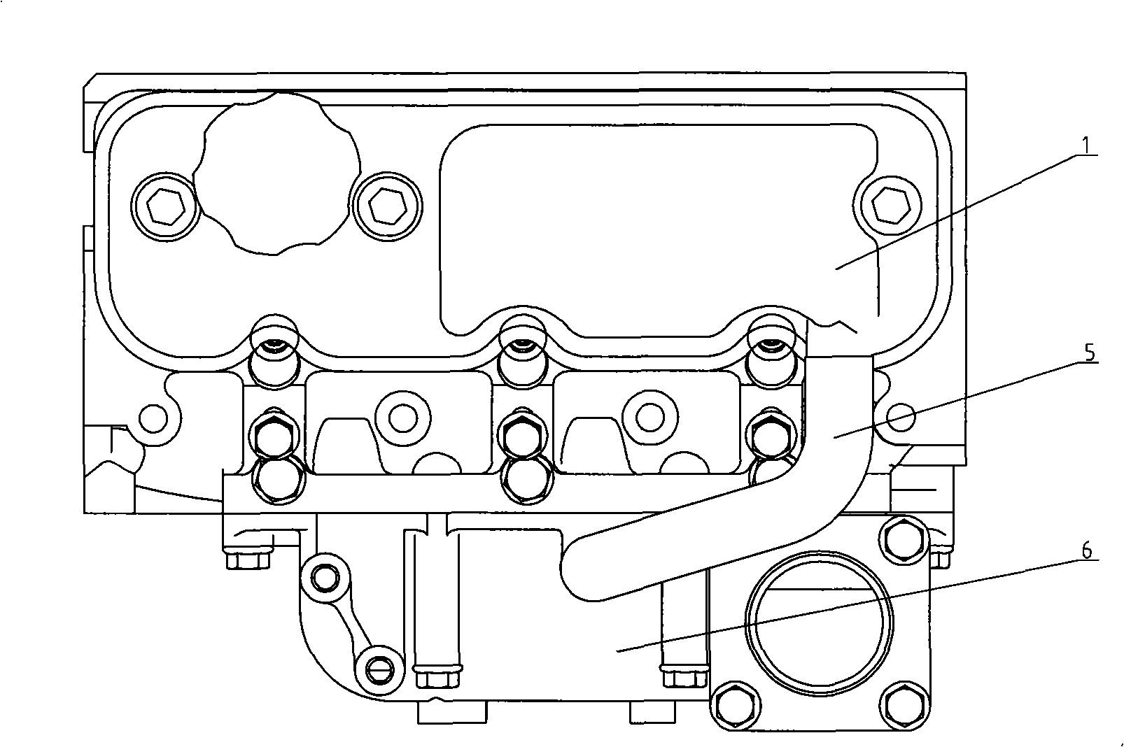
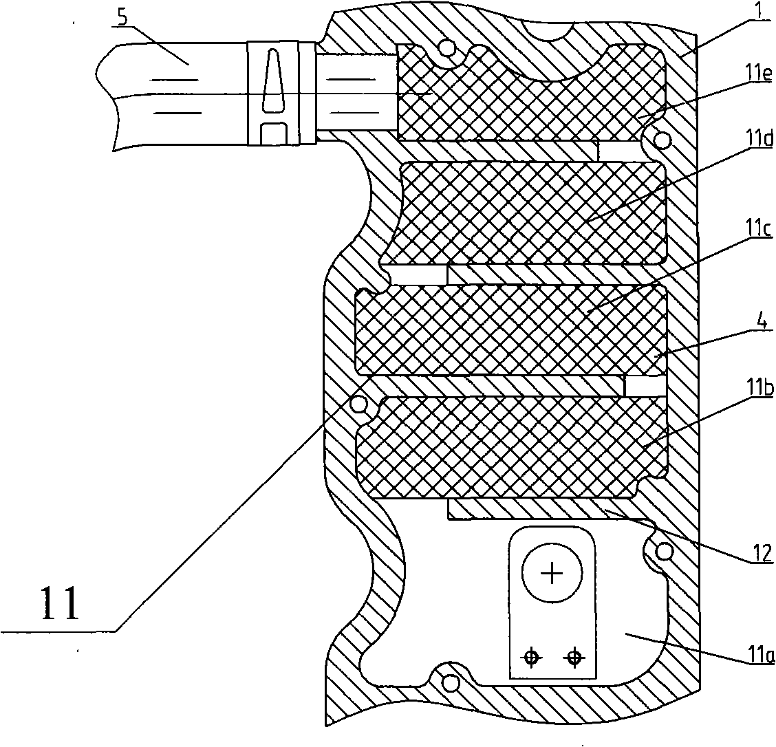

Image

  • Engine ventilating device
  • Engine ventilating device
  • Engine ventilating device

Examples


Embodiment Construction

[0016] Below the present invention will be further described in conjunction with the embodiment in the accompanying drawing:

[0017] Such as figure 1 , figure 2 , image 3 As shown, it includes cylinder cover 1, separation chamber 11 (11a, 11b, 11c, 11d, etc. represent several small separation chambers), baffle plate 12, respirator cover plate 2, oil collection groove 2a, oil drain hole 2b, Respirator spring 3a, spring plate 3b, capture material 4, respirator rubber hose 5, air intake pipe 6, etc.

[0018] In the present invention, several baffles 12 are reasonably arranged on the wall surface of the inner top plate of the cylinder cover 1, and a plurality of separation chambers 11 (11a, 11b, 11c, 11d, 11e, etc.) are arranged to form a tortuous circuit of the oil mist flow. The interior is filled with capture material 4 and covered with a respirator cover plate 2 . When the gas flows through, the oil mist in the gas is easily captured and separated into oil liquid and ga...


PUM


Abstract

The invention relates to an engine breather for improving the performance of a whole internal-combustion engine and being favorable for environmental protection. The invention is characterized in that a cylinder cover is provided with a plurality of shutters and separation chambers filled with catch materials and covered by an inspirator cover. The inspirator cover is provided with an oil-gathering groove. The bottom of the oil-gathering groove is provided with a plurality of oil drain holes. The inspirator cover is provided with an inspirator pore that is a communication pore canal for a crankcase and an intake manifold. An inspirator spring piece and a spring piece binder plate are arranged in the inspirator pore. The engine breather can prevent oil mist in the crankcase of the engine from being discharged to outside, thus effectively stopping elaioplast in the oil mist from entering a combustion chamber and avoiding carbon and cold smoke caused by the oil burning of the engine. And the engine oil consumption and the discharge amount of carbon granule are increased.

Description

technical field [0001] The invention relates to a ventilation device for an engine crankcase to improve the performance of the entire internal combustion engine and be beneficial to environmental protection. Background technique [0002] In the prior art, the ventilation device of the crankcase of the engine is relatively simple. Usually, a steel wire filter screen is installed on the oil filler cap cover, and some small holes communicate with the atmosphere. Some also have a small hole at the highest point of the cylinder cover. The rubber tube communicates with the outside world, so that the oil mist gas in the crankcase can directly communicate with the atmosphere, but this kind of structure is easy to pollute the air around the engine, and oil droplets will form sludge on the ground. In addition, there is also a rubber diaphragm valve installed at the highest point in the cylinder head cover to allow the outlet gas to flow into the intake pipe, and the oil gas contains m...

Claims


Application Information

Patent Timeline
Patent Type & Authority Applications(China)
IPC IPC(8): F01M13/04
Inventor 肖亨琳
Owner WUXI KIPOR POWER CO LTD
Learn More