Stepped control type flux valve

A step control, flow valve technology, applied in the direction of using electric device flow control, lift valve, valve details, etc., can solve problems such as unstable system operation, and achieve the effect of small valve body volume

Inactive Publication Date: 2008-09-24
BEIJING XINGHANG MECHANICAL ELECTRICAL EQUIP
View PDF0 Cites 6 Cited by
  • Summary
  • Abstract
  • Description
  • Claims
  • Application Information

AI Technical Summary

Problems solved by technology

In some occasions that require a stable output flow, especially where a precise output flow is required, if the output flow fluctuates, it will cause the entire system to work unstable.

Method used


Image

  • Stepped control type flux valve
  • Stepped control type flux valve

Examples


Embodiment Construction

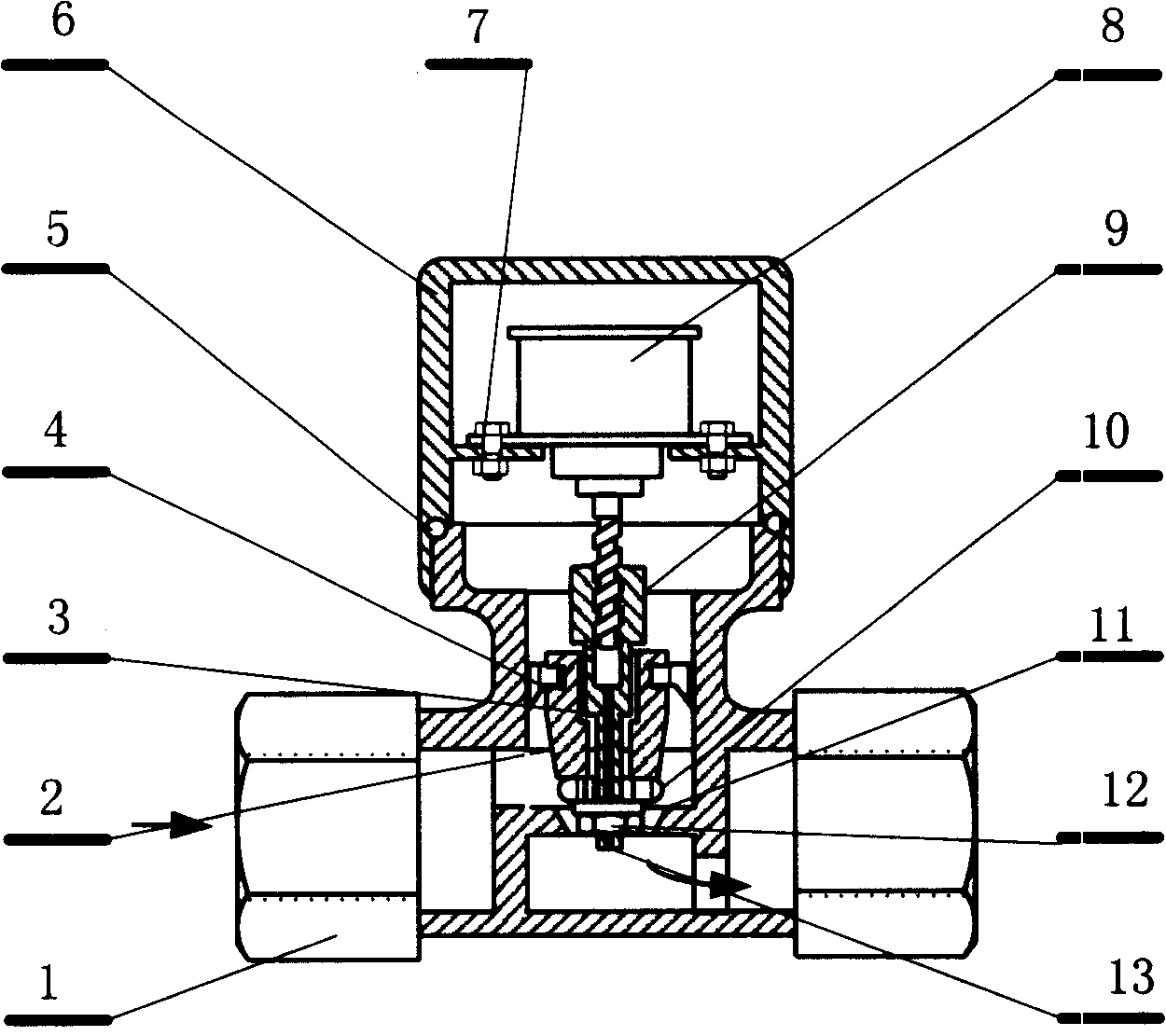
[0009] figure 2 It is a straight-through stepping valve structure. The valve body (1) can be made of stainless steel or copper. The interfaces at both ends can be designed according to the requirements of the equipment. For example, it can be processed into outer wire or inner wire, or it can be processed into live wire connection method. There is a water outlet (11) in the valve body (1), and the upper part of the valve body (1) is connected with the sealing cover (6) through threads and the valve cover sealing ring (5), and a stepping motor is installed in the sealing cover (6) (8), the output shaft of the stepper motor (8) is connected with the linkage rod (9) through threads, the transmission rod (9) is installed in the inner cavity of the piston (2), and is slidingly connected with the inner cavity of the piston (2), and the transmission A sealing ring (10) is installed on the lower part of the rod (9), and the sealing ring (10) is fixed on the lower part of the transmi...


PUM


Abstract

A flow valve of step control belongs to the automatic flow control technical field of electromechanical integration. The system consists of a control part and an execution part, which is characterized in that an analog signal sent by a sensor is converted into a digital signal via an AD chip and then is transmitted into a kernel control part to be processed. The kernel control part compares the signal with a preset parameter and then outputs the control dictates. Driven by a power amplifier, a step motor is arranged inside a sealed flow valve cover of step control.

Description

technical field [0001] A step control type flow valve belongs to the technical field of flow automatic control of electromechanical integration. technical background [0002] The existing liquid flow automatic control technology, such as the control of water and oil flow, generally uses a two-position solenoid valve or asynchronous motor as its actuator, so the volume is relatively large, which is not suitable for some applications that require a small volume. It is used in products with a very compact, fine and self-contained internal structure. Since the existing technology is a bit structure, there are only two actions of opening and closing, and the output flow is fluctuating. In some occasions that require stable output flow, especially precision output flow, if the output flow fluctuates, it will cause the instability of the entire system. Contents of the invention [0003] The purpose of the present invention is to provide a technical solution of a step-control fl...

Claims


Application Information

Patent Timeline
IPC IPC(8): F16K1/00F16K31/04G05D7/06
Inventor 全龙浩董民超
Owner BEIJING XINGHANG MECHANICAL ELECTRICAL EQUIP
Why Eureka
Try Eureka