Supercharge Your Innovation With Domain-Expert AI Agents!

Absolute encoder

An absolute encoder and absolute encoding technology, applied in the field of absolute encoders, can solve the problems of increased error possibility, excitation magnetic flux change, sensor size increase, etc., to eliminate errors in reading absolute codes, correct temperature characteristics, reduce small size effect

Active Publication Date: 2008-09-24
OKUMA CORP
View PDF2 Cites 16 Cited by
  • Summary
  • Abstract
  • Description
  • Claims
  • Application Information

AI Technical Summary

Problems solved by technology

Meanwhile, from a size point of view, when an E-shaped field core is used, the field cores 505a and 505b need to be larger than the size in the tangential direction of the gear along which the magnetic sensors 504a-504d and 504e-504n are arranged. , and the size of the sensor increases
On the other hand, since permanent magnets and windings are used for the excitation device, there is a high possibility that the field magnetic flux varies due to the temperature characteristics of the permanent magnets or the temperature change of the winding resistance
Therefore, the problem is that when the temperature changes, the output levels of the magnetic sensors 504e-504n for detecting the binary cyclic random number sequence code fluctuate, which increases the possibility of error in the detection of the binary cyclic random number sequence code

Method used


Image

  • Absolute encoder
  • Absolute encoder
  • Absolute encoder

Examples


Embodiment approach 1

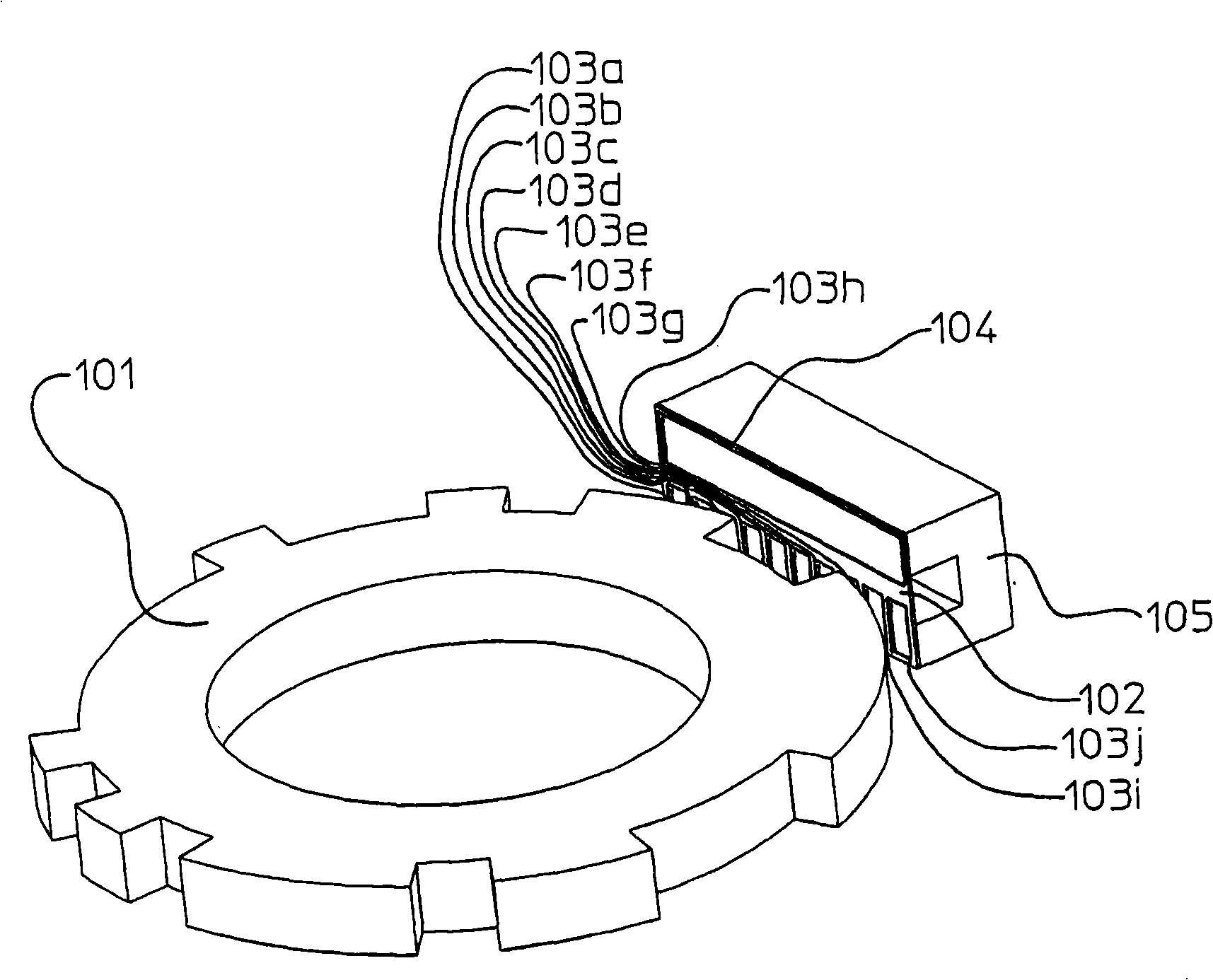
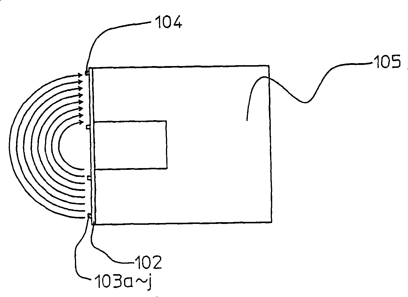
[0021] Next, Embodiment 1 of the present invention will be described with reference to the drawings. figure 1It is a perspective view showing an example of the absolute code detection unit of the absolute encoder in this embodiment. The binary cyclic random number sequence encoding disk 101 has an unillustrated shaft fixed thereon so as to be rotatable. Each detection winding 103a-103j made of a conductor pattern, and an excitation winding 104 made of a conductor pattern are arranged on the printed circuit board 102, and the printed circuit board 102 is relatively binary by a predetermined gap amount. The cyclic random number sequence encodes the arrangement on the outer peripheral surface of the disc 101 . A U-shaped field core 105 made of a magnetic member such as a ferrite core is arranged on the rear surface of the printed circuit board 102 . That is, when the U-shaped field core 105 is cut by a plane passing through the rotational axis of the code disk 101 , a U-shaped...

Embodiment approach 2

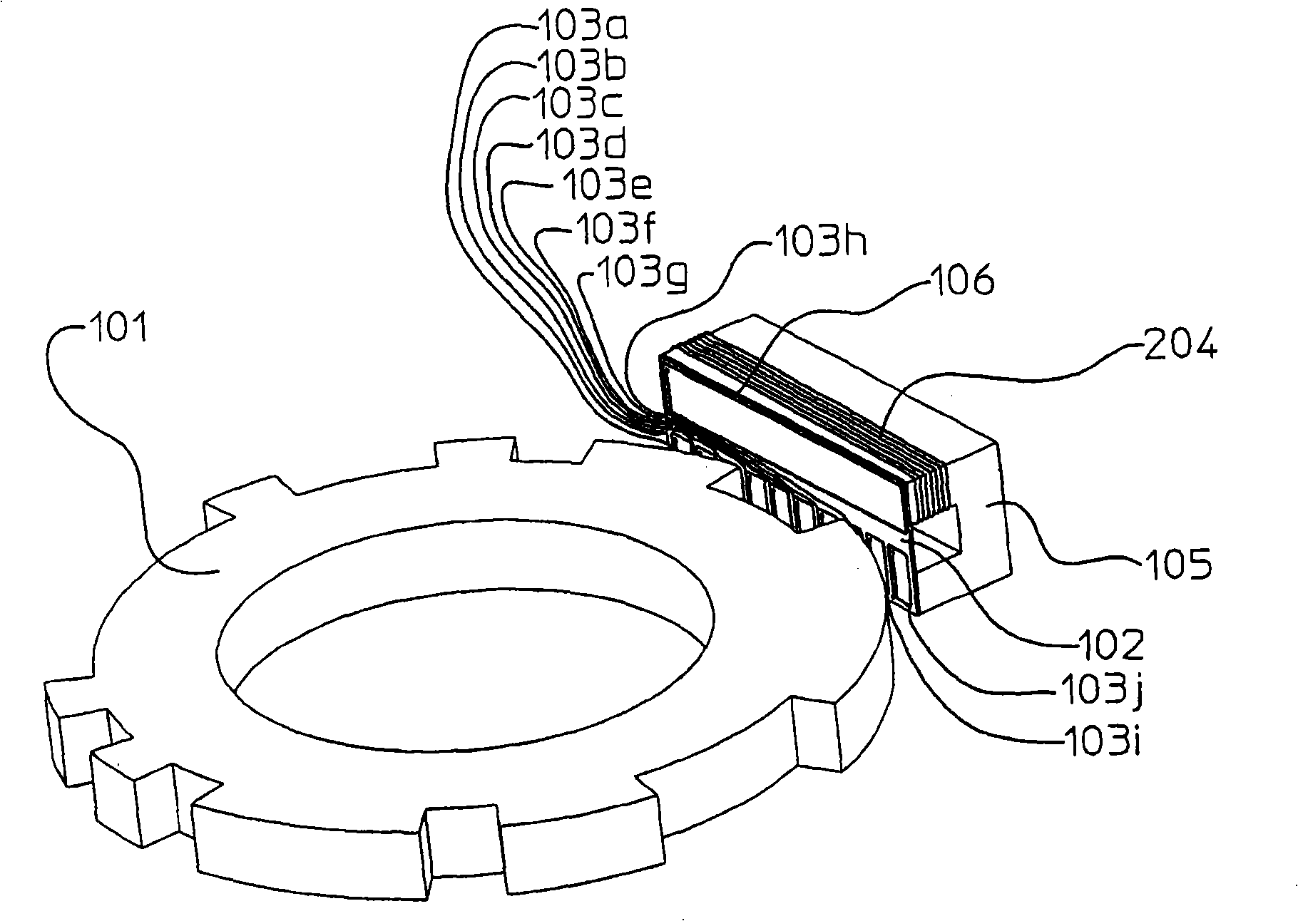
[0025] image 3 to show the figure 1 A perspective view of an example of a detection unit of an absolute encoder in Embodiment 2 in which the absolute encoder is different from that of FIG. exist image 3 in, with figure 1 Like components are assigned the same numbers and marks. However, as with figure 1 One difference is that the excitation winding 204 is directly wound on the excitation core 105 , and the upper winding on the printed circuit board 102 is the excitation flux detection winding 106 . Correspondingly, with figure 2 The same magnetic flux in is formed by the field winding 204 .

[0026] In this way, the excitation magnetic circuit formed is basically the same as figure 1 in the same. Therefore, the role of the field magnetic flux detection winding 106 will be explained here. The excitation winding 204 and the excitation core 105 made of magnetic materials have the following characteristics: when the temperature changes, the winding impedance, magnet...


PUM


Abstract

A printed circuit board on which are laid out detection windings and an excitation magnetic flux detection winding formed of conductor patterns is disposed so as to be spaced a predetermined gap quantity from a binary cyclic random number sequence code plate which is rotatably disposed. A U-shaped exciting core on which an excitation winding is wound is disposed on the back surface side of the printed circuit board. The detection windings detect and output, as voltage values, reluctance changes as which excitation magnetic fluxes generated from the excitation winding fluctuate between this excitation winding and the concave / convex portion of the binary cyclic random number sequence code plate. Reduction of precision due to interferences between the excitation magnetic fluxes for detecting an absolute code and other excitation magnetic flux is thereby prevented.

Description

[0001] References to related applications [0002] This application claims priority from Japanese Patent Application No. 2007-073247 filed on March 20, 2007, the entire contents of which are incorporated herein by reference. technical field [0003] The invention relates to an absolute encoder with a scale section, wherein the absolute code is etched on the surface of a magnetic material. Background technique [0004] The following will refer to Figure 7 Describe prior art. Figure 7 An absolute encoder described in Patent Document 1 (Japanese Patent Publication No. JP-A-5-118874) is shown. The encoder disk 7 includes an incremental gear shape component for detecting a two-phase sinusoidal signal, and concave / convex portions conforming to a binary cyclic random number sequence for detecting an absolute pattern. In addition, magnetic sensors 5s and 5c made of magnetoresistive elements and detecting two-phase sinusoidal signals, and magnetic sensors 1a-1d, 2a-2d, 3a-3d, and ...

Claims


Application Information

Patent Timeline
Patent Type & Authority Applications(China)
IPC IPC(8): G01D5/249
CPCG01D5/2497G01D5/145G01D2205/80G01D2205/774
Inventor 林康一福井宪之
Owner OKUMA CORP
Features
  • R&D
  • Intellectual Property
  • Life Sciences
  • Materials
  • Tech Scout
  • Unparalleled Data Quality
  • Higher Quality Content
  • 60% Fewer Hallucinations
Learn More