
Optical device

A technology for optical equipment and optical components, applied in the directions of optics, optical components, nonlinear optics, etc., can solve the problem of difficult heat transfer of the thin-film heat source 422, and achieve the effect of eliminating the deterioration of wavelength conversion characteristics, preventing characteristic changes, and preventing deformation.

Inactive Publication Date: 2014-02-05
CITIZEN WATCH CO LTD
View PDF5 Cites 2 Cited by
  • Summary
  • Abstract
  • Description
  • Claims
  • Application Information

AI Technical Summary

Problems solved by technology

Also, since the thin film heat source 422 is not in contact with the silicon substrate 401 due to the groove 402 of the silicon substrate 401, the heat of the thin film heat source 422 is hardly transferred to the silicon substrate 401.

Method used


Image

  • Optical device
  • Optical device
  • Optical device

Examples


Embodiment Construction

[0066] An optical device equipped with a wavelength conversion element that converts incident light into a second harmonic wave will be described as an example with reference to the following drawings. However, please note that the technical scope of the present invention is not limited to the drawings and the embodiments described below.

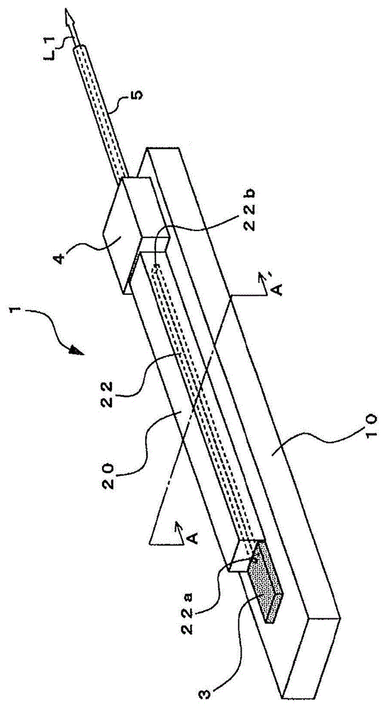
[0067] figure 1 It is a schematic diagram showing the overall structure of the optical device 1 .

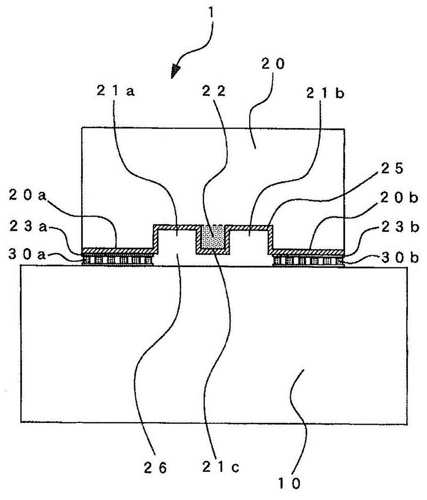
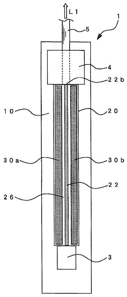
[0068] Such as figure 1 As shown, the optical device 1 includes: a plate-shaped silicon substrate 10, a wavelength conversion element 20 as an optical element bonded to the silicon substrate 10, a semiconductor laser 3 bonded to the silicon substrate 10 to emit laser light, and a semiconductor laser 3 bonded to the silicon substrate. 10, an auxiliary substrate 4 for fixing the optical fiber 5, and the like. The optical device 1 is equipped with a ridge-type wavelength conversion element as an optical element, and a heat source for temper...


PUM


Abstract

Provided is an optical device wherein a gap is formed between an optical waveguide path and a substrate without disposing a depression, etc., upon the substrate, and whereon stress is not applied to an optical element even if heat is received from a heater for temperature adjustment. An optical device comprises: a substrate; an optical element further comprising an optical waveguide path which is formed on a surface which faces the substrate; a bonding part which is formed on the substrate to be located sandwiching the optical waveguide path; a heater which is formed on at least either the optical element or the substrate to heat the optical waveguide path; and a micro-bump structure which is configured from a metallic material. The bonding part and the optical element are bonded across the micro-bump structure such that a gap is formed between the optical waveguide path and the substrate.

Description

technical field [0001] The present invention relates to an optical device in which an optical element forming an optical waveguide is bonded to a substrate. Background technique [0002] Short-wavelength laser light sources are widely commercialized in the fields of laser projectors and high-density optical storage. A short-wavelength laser light source outputs blue or green laser light through a wavelength conversion element that converts fundamental infrared light excited by a laser element of an optical device into a second harmonic wave. Although crystal materials such as LN (lithium niobate: LiNbO3) and LT (lithium tantalate: LiTaO3) are used for wavelength conversion elements, the conversion efficiency of higher harmonics is temperature-dependent, and the conversion efficiency varies greatly according to changes in ambient temperature. characteristics. [0003] Figure 26(a) It is a graph showing an example of a change in the higher harmonic output (HFO) with respect...

Claims


Application Information

Patent Timeline
IPC IPC(8): G02F1/03G02B6/122G02F1/377
CPCG02F1/377G02F2203/21G02F1/3505G02B6/12
Inventor 井出昌史野崎孝明依田薰阿部洋辅
Owner CITIZEN WATCH CO LTD
Learn More