Electronic label antenna

An electronic tag and antenna technology, applied in the field of electronic tags, can solve the problems of inconvenient use, easy damage of electronic tags, inconvenient use and management of rod objects, etc., and achieve the effect of convenient use and storage, simplified structure and compact structure

Inactive Publication Date: 2008-09-24
CYG CONTRON
View PDF0 Cites 7 Cited by
  • Summary
  • Abstract
  • Description
  • Claims
  • Application Information

AI Technical Summary

Problems solved by technology

This brings inconvenience to the use and management of rod objects. At the same time, the structure of such rod objects is not compact enough, and the use is not convenient enough.
[0006] Another example is the temporary grounding wire plug in the field of microcomputer error prevention for power line systems. The needs of modern digital management of power station users require us to assign an electronic identity to each temporary grounding wire for management. Undoubtedl

Method used


Image

  • Electronic label antenna
  • Electronic label antenna
  • Electronic label antenna

Examples


Embodiment Construction

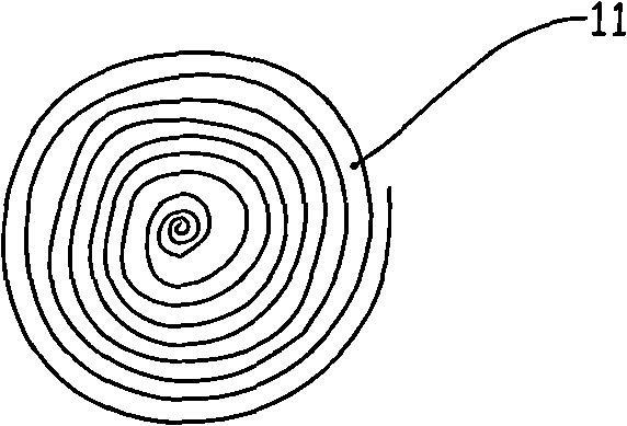
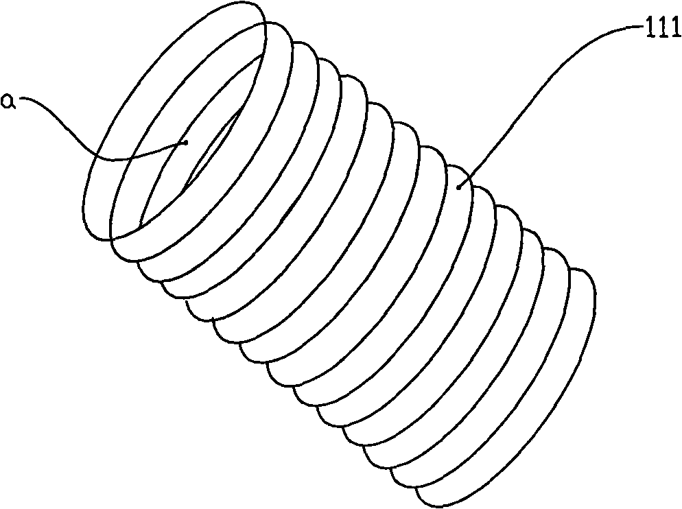
[0019] see image 3 , the electronic tag antenna 111 is used to couple with the read head antenna in the read head device, and transmit the identity information signal contained in the tag circuit. The electronic tag antenna 111 is a coil wound by a wire; the coil of the electronic tag antenna 111 is spirally wound along the axial direction to form a ring, and the ring coil has a hollow part a.

[0020] see Figure 4 , which is an application example of the electronic tag antenna of the present invention. The electronic tag antenna 111 is loop-wound on a rod-shaped object 3 that requires electronic tag management, that is, the rod-shaped object 3 passes through the hollow part a of the electronic tag antenna 111 . A tag circuit (not shown) is bound to the electronic tag antenna 111 . After the electronic tag antenna 111 is installed on the rod-shaped object 3, the structure of the rod-shaped object 3 is more compact and simple; the important thing is that it is not necessary...


PUM


Abstract

The invention relates to the field of E-tag for object identification, in particular to an antenna on the E-tag. The E-tag antenna couples with a reading head antenna in a reading head device to transmit the identification information signals which are contained by the tag circuit; the E-tag antenna is a coil intertwined with a lead, wherein, the coil is a ring shape. As the invention arranges the tag antenna to be the ring shape, under the circumstances that the position holding axis of the antenna coil of reading head equipment for reading the E-tag is parallel to the axis of the tag antenna and keeps a proper distance, the invention can acquire the readability at any direction of the surrounding 360 degrees of the ring-shaped E-tag antenna; when the reading head equipment is fixed, a ring-shaped E-tag code block is sheathed outside a rod object requiring identification, the rod object can get close to the reader at any position in the surroundings to acquire reliable reading results, thus being able to simplify the rob object structure without circumferential directional location of the rod object.

Description

technical field [0001] The invention relates to the field of electronic tags used for object identification, in particular to antennas on the electronic tags. Background technique [0002] Electronic tags are more and more widely used because of their special global unique identity code value characteristics and extremely convenient implementation modes such as passive solutions. Electronic tags usually include electronic tag antennas and tag circuits. Electronic tags are divided into chip electronic tags ( Such as IC type electronic tags) and chipless electronic tags (such as SAW radio frequency tags) two categories. The mainstream of electronic label application is electronic label with chip (IC type electronic label). Most of its label circuits have been integrated into IC to reduce costs, and the passive type (passive type) is the most commonly used. SAW radio frequency tags are also increasingly valued because of their gradual cost reduction and high environmental adap...

Claims


Application Information

Patent Timeline
IPC IPC(8): H01Q7/00H01Q7/06G06K19/077
Inventor 栗新胡光耀高波
Owner CYG CONTRON
Why Eureka
Try Eureka