Mixer and method of mixing

A technology of mixing and mixing chamber, which is applied in the field of high-energy mixing to achieve the effect of maximizing the gap

Inactive Publication Date: 2008-09-24
MAELSTROM ADVANCED PROCESS TECH
View PDF0 Cites 8 Cited by
  • Summary
  • Abstract
  • Description
  • Claims
  • Application Information

AI Technical Summary

Problems solved by technology

In other respects such as the proportion of time material passes in the low stress region of the extruder screw, the twin screw extruder is subject to similar limitations as the single screw extruder
[0008] It can thus be seen that, in general, the types of m

Method used


Image

  • Mixer and method of mixing
  • Mixer and method of mixing
  • Mixer and method of mixing

Examples


Embodiment Construction

[0060] It should be understood that terms such as "rotor", "stator", "kneader", "kneading" and "coolant" are used in the text of this description for purposes of illustration only and are not to be construed as limiting definition.

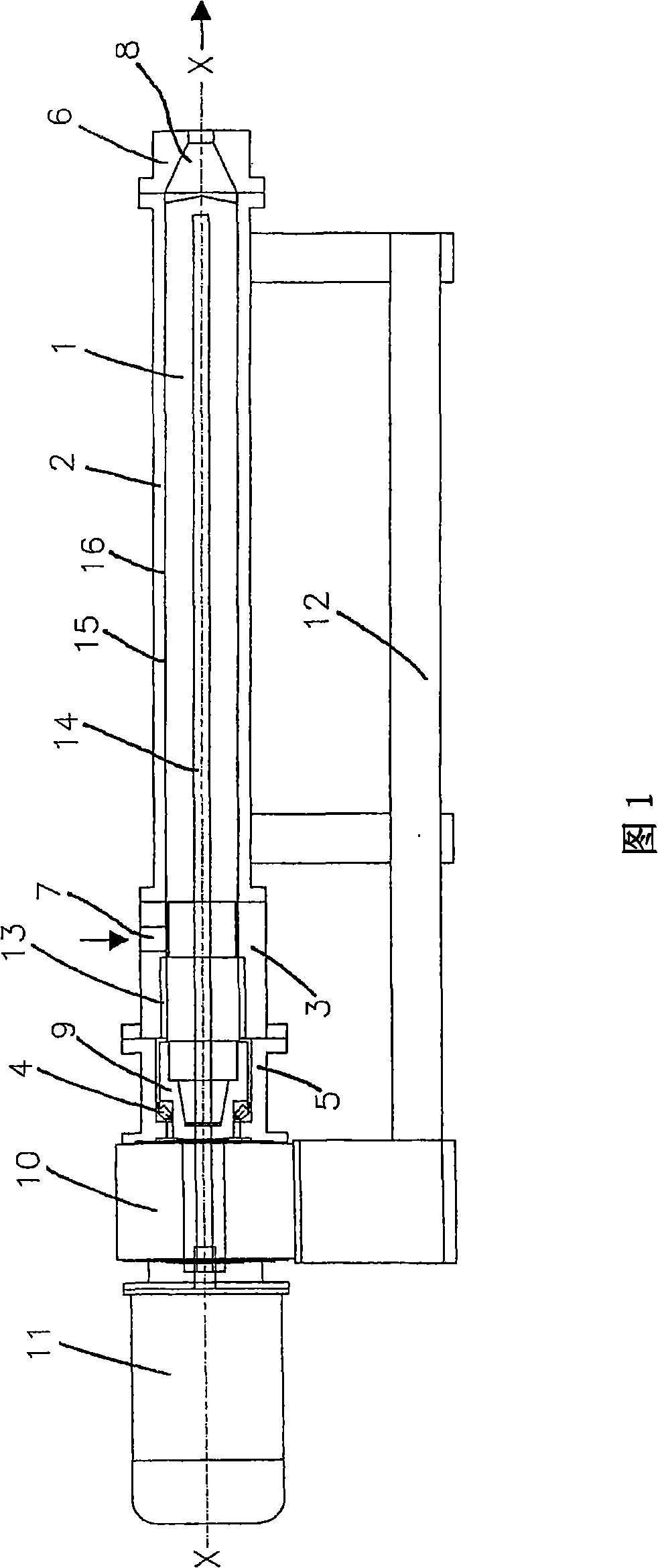
[0061]Referring to Figure 1, the mixer described comprises a rotor 1 (first mixing part) mounted in a stator housing 2 (second mixing part) and in an inlet housing 3 and supported on a drive shaft In the ring 9 said drive collar 9 is supported in the bearing 4 in the gearbox 5 . The rotor 1 rotates around the axis XX. The inlet housing 3 is connected to the stator housing 2 and the gear box 5 is connected to the inlet housing 3 . An electric motor 11 drives the drive collar 9 in rotation through a gear reducer 10 . The stator housing 2 and the gear reducer 10 are mounted on a support frame 12 . An outlet housing 6 is connected to the opposite end of the stator housing. The aforementioned inlet housing 3 defines a mixer inlet 7 and the aforeme...


PUM


Abstract

A dynamic mixer in which two members (1,2) are rotated relative to each other about a predetermined axis (XX), the members having facing surfaces (15, 16) which extend axially and between which is defined a mixing chamber through which a flow path extends between an inlet (7) for material to be mixed and an outlet (8). An array of two or more mixing formations is defined on at least one of the facing surfaces (15, 16) which extend radially towards the facing surface of the other element (15, 16) and which act to mix material within the mixing chamber, and which extend axially generally parallel to the axis. A mixing formation thus defined is configured to provide a constricting flow passage followed by an expanding flow passage to material present in the mixing chamber as the first and second members are relatively rotated, with the mixing formations located around the axis on any plane perpendicular to the axis so as to provide a generally net balance of the radial loads imparted by material present in the space between the surfaces. The material within the mixing chamber is subjected to high extensional and or shear stresses arising from the circumferential drag flow induced between the closely separated facing surfaces, while being permitted to flow axially between the widely separated flowing surfaces. Dispersive mixing and distributive mixing effects are thereby obtained.

Description

technical field [0001] The present invention relates to mixing and provides a new mixing device and mixing method. In particular, the invention relates to high energy mixing of viscous materials. It should be understood that the term "mixing" includes the processing of a single material. Background technique [0002] Mixing operations are generally understood to include two distinct actions: dispersive mixing and distributive mixing. During dispersive mixing, individual parts of the materials being mixed, whether solid or fluid, are mixed, said materials having their respective geometric shapes modified by the application of stress. When increasing the number of individual parts, it usually manifests as a decrease in the average size of the individual parts. During distributive mixing, whether the material is solid or fluid, the individual parts of the material are brought together in order to obtain a spatial consistency of the various material parts with respect to each...

Claims


Application Information

Patent Timeline
IPC IPC(8): B01F3/10B01F9/06B01F7/12B01F9/08B01F23/47B01F25/60B01F27/74B01F29/63B01F29/64
CPCB01F15/0251B01F7/00833B01F2015/0221B01F7/008B01F15/0243B01F9/06B01F15/0201B01F3/10B01F7/00825B01F9/08B01F23/47B01F27/272B01F27/2723B01F27/2724B01F29/63B01F29/64B01F35/715B01F35/71B01F35/7176B01F35/71775
Inventor 克里斯·布朗
Owner MAELSTROM ADVANCED PROCESS TECH
Why Eureka
Try Eureka