Ammonia-spraying grid device for SCR-method flue gas denitrification, and SCR-method flue gas denitrification process

An ammonia injection grille and flue gas technology, applied in separation methods, greenhouse gas capture, climate sustainability, etc., can solve the problems affecting the mixing distance and denitration efficiency of the ammonia injection grille, increase the resistance of flue gas, poor injection rigidity, etc. To achieve the effect of reducing smoke resistance and mixing distance, reducing smoke resistance and reducing mixing distance

Active Publication Date: 2009-12-16
HUADIAN ENVIRONMENTAL PROTECTION ENG & TECH
View PDF0 Cites 30 Cited by
  • Summary
  • Abstract
  • Description
  • Claims
  • Application Information

AI Technical Summary

Problems solved by technology

so to NH 3 The mixing with the flue gas has a certain promoting effect, but due to the high speed of the flue gas here, the resistance of the flue gas is also greatly increased
In addition, the ammonia injection grid with holes on the metal tube bundle is used. Due to the poor injection rigidity of the small holes, the mixing effect of the injected ammonia and flue gas is poor, which affects the mixing distance and denitrification efficiency of the ammonia injection grid.

Method used


Image

  • Ammonia-spraying grid device for SCR-method flue gas denitrification, and SCR-method flue gas denitrification process
  • Ammonia-spraying grid device for SCR-method flue gas denitrification, and SCR-method flue gas denitrification process
  • Ammonia-spraying grid device for SCR-method flue gas denitrification, and SCR-method flue gas denitrification process

Examples


Embodiment Construction

[0030] The present invention will be described in detail below in conjunction with the accompanying drawings. The description in this part is only exemplary and explanatory, and should not have any limiting effect on the protection scope of the present invention.

[0031] It should be noted that this embodiment is described by taking a coal-fired boiler in a power station as an example, but it is not limited to other combustion equipment.

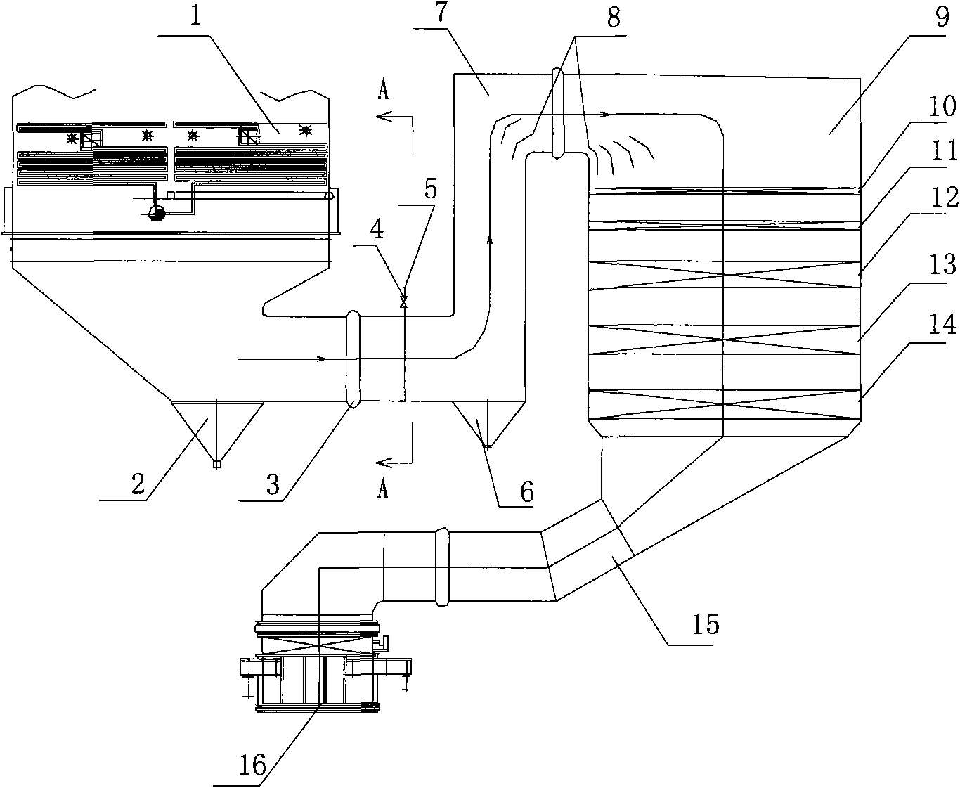
[0032] like figure 1 The schematic diagram of the flue gas denitrification process of the SCR method is shown. The flue gas after boiler combustion is discharged from the economizer 1 and then enters the flue 7 at the entrance of the denitrification reactor. The reactor inlet flue ash hopper 6 is arranged at the corner of the reactor inlet flue, the purpose of which is to collect the smoke and discharge the flue gas system to prevent the dust from abrading and clogging the catalyst and the downstream equipment of the denitrification device....


PUM


Abstract

The invention discloses an ammonia-spraying grid device for SCR-method flue gas denitrification, which comprises an ammonia-spraying grid consisting of bundles of metal pipes, wherein each metal pipe is provided with a nozzle in the radial direction; the nozzle is communicated with the metal pipe; and the included angle between the opening direction of the nozzle and the flow direction of flue gas is between 0 and 90 degrees. The invention also discloses an SCR-method flue gas denitrification process adopting the ammonia-spraying grid device. The process adopts the ammonia-spraying grid to distribute ammonia/air gas mixture sprayed into an inlet flue of a denitrification reactor, and adjusts ammonia spray distribution according to the concentration of NOx in the inlet flue of the reactor so as to mix the NOx in the flue gas with NH3 sprayed in well, thus the mixing effect of the NH3 and the flue gas as well as denitrification efficiency can be effectively improved. A grid-type ammonia spraying-distributing-mixing device of the invention has the advantages of simple structure, low mixture resistance, good distribution effect, insusceptibility to ash deposition, capability of effectively protecting ammonia-spraying grid nozzles from wear, reducing the mixture distance of ammonia and the flue gas in an inlet of the denitrification reactor, improving the utilization rate of denitrification catalysts, reducing the height of the denitrification reactor and reducing the resistance of a flue gas denitrification system, thereby greatly reducing the unit cost of flue gas denitrification.

Description

technical field [0001] The invention relates to an SCR flue gas denitrification process and equipment, in particular to an ammonia injection grid device for SCR flue gas denitrification, which is also applicable to the ammonia injection grid device in flue gas exhausted by various combustion equipment. Background technique [0002] NO x The treatment of air pollution has always been the focus of environmental protection in most countries in the world, and the pollutants it produces are one of the largest pollution sources that cause damage to the ecological environment in our country. At present, it has become the top priority of air pollution control in our country. [0003] for NO x At home and abroad, the selective catalytic reduction (SCR) flue gas denitrification process is mainly used. This process has high denitrification efficiency and no secondary pollution. It is widely used in various combustion equipment. The denitrification principle is the use of NH 3 (Liquid...

Claims


Application Information

Patent Timeline
Patent Type & Authority Applications(China)
IPC IPC(8): B01D53/86B01D53/76B01D53/56
CPCY02C20/10
Inventor 李建浏胡永锋陶爱平吕同波陈鹏张国新张兵兵王淑荣
Owner HUADIAN ENVIRONMENTAL PROTECTION ENG & TECH
Why Eureka
Try Eureka