Rotating extrusion concrete filling pile construction method and equipment

A construction method and concrete technology, applied in drilling equipment, earthwork drilling, sheet pile walls, etc., can solve the problems of high construction cost, low construction efficiency, large waste of concrete, etc., to achieve easy popularization, reduce construction cost, cost-effective pile effect good effect

Inactive Publication Date: 2008-10-01
邱树军
View PDF0 Cites 6 Cited by
  • Summary
  • Abstract
  • Description
  • Claims
  • Application Information

AI Technical Summary

Problems solved by technology

[0002] At present, long helical pumping superfluid concrete pouring piles are often used in the foundation treatment of high-rise buildings. The main problems of this method are: 1. The soil piles are obtained by auger drilling, which has no compaction effect on the soil between the piles, and has no effect on the following The friction-based composite foundation cannot give full play to the strength effect of the pile body
2. Restricted by the technology of construction machines and tools, the application range of the formation is relatively small, only suitable for soft clay, clay and silty sand formations, not suitable for soil layers with high gravel content, and the strength is 180-220KN / m 2 Above the clay layer and weathered and broken rock layer
3. The long auger drill pipe rotates continuously in the hole, the diameter of the loose ground is larger, the concrete filling coefficient is 1.5, the waste of concrete is large, and the construction cost is high
4. The long auger drill rod rotates continuously and rubs against the hole wall, resulting in high power consumption and low construction efficiency

Method used


Image

  • Rotating extrusion concrete filling pile construction method and equipment
  • Rotating extrusion concrete filling pile construction method and equipment
  • Rotating extrusion concrete filling pile construction method and equipment

Examples


Embodiment Construction

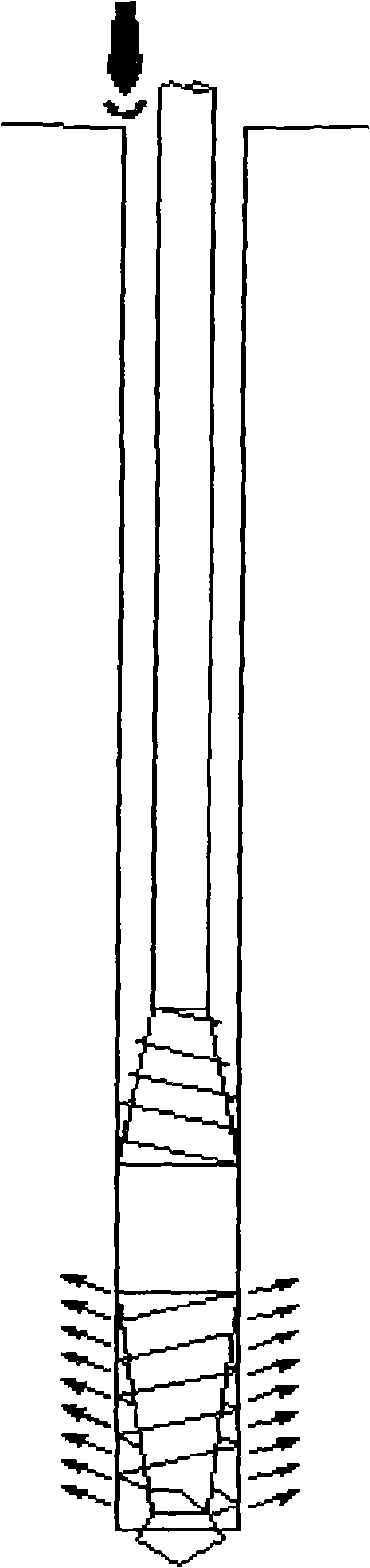
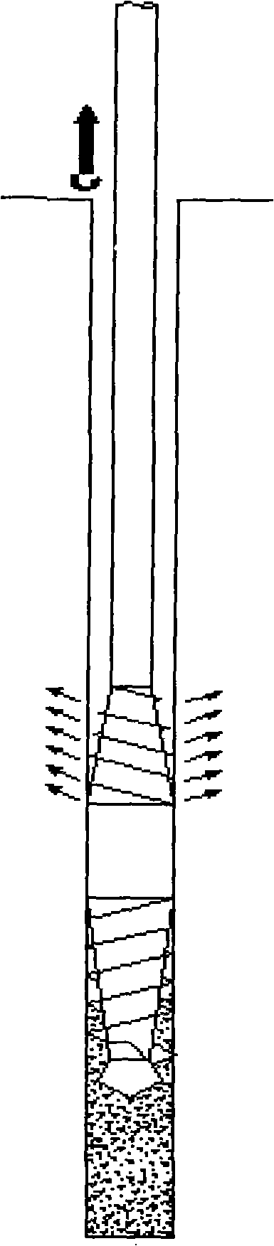
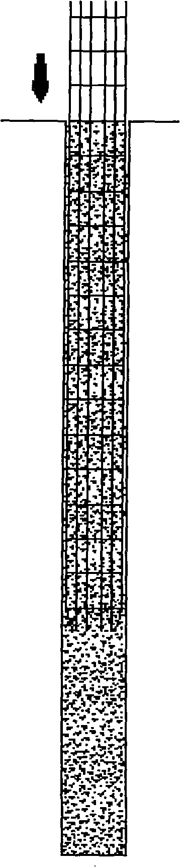
[0015] The rotary extrusion concrete pouring pile construction method uses a drilling tool with an olive-type drill bit to drill holes. Through the rotary extrusion of the drill bit on the soil, a drill hole with the surrounding soil compacted to the design depth is formed, and then reversed to lift Drill pipe, while lifting the drill pipe, pump superfluid concrete into the hollow drill pipe. After the drill pipe is raised, it vibrates and inserts into the reinforcement cage. In the construction method of the above rotary extrusion concrete pouring pile, the concrete is concrete with a slump of 22-25cm. The borehole is formed by the rotary extrusion of the olive drill bit on the soil, which does not need to take soil and has a good compaction effect on the surrounding soil. After the concrete pouring pile is drilled, concrete is pumped into the center of the drill pipe. Realize the used equipment of rotary extruding concrete cast-in-situ pile construction method of the presen...


PUM


Abstract

A rotating squeezing concrete filling pile construction method, uses boring tool solid boring with olive type solid borer to drill, rotatably squeezes the soil body to form a solid boring whose surroundings soil body is pressed to the designed deepness, and then reversely turning and lifting the drill stem, meanwhile pumping ultra-fluid state concrete in the hollow-drill stem, vibratedly inserting the drill stem in a reinforcing steel cage after lifting out the drill stem. Boreholes are formed by using olive type solid borer to rotating squeeze the soil body, which does not need to take out earth, has a favorable pressing dense function to surroundings soil body, and rotatably squeezes the concrete filling pile borehole as an once creating pore. Adopting the inventive rotatably squeezing dense soil body pore-creating method, the pile surroundings soil body is stabilized by densification, the compactness of the pile surroundings soil body is improved about 30%, the pile side friction resistance is improved about 30%, the pile end support force is improved about 50-70%; the unconsolidated formation concrete filling coefficient is only 1.25, the construction cost is reduced, which has good pile-formation effect and can improve work efficiency for about 20-30%; the method is suitable for hard and compact clay layer, soil layer containing larger gravel amount and air slaking pulverize rock bedding, meanwhile has economy and environment protection effect; the invention has advantages of simple structure, low fabrication cost, being apt to popularize and spread, and being widely used in concrete filling pile construction.

Description

Technical field: [0001] The invention relates to a construction method and equipment for building pile foundations. Background technique: [0002] At present, long helical pumping superfluid concrete pouring piles are often used in the foundation treatment of high-rise buildings. The main problems of this method are: 1. The soil piles are obtained by auger drilling, which has no compaction effect on the soil between the piles, and has no effect on the following The friction-based composite foundation cannot give full play to the pile strength effect. 2. Restricted by the technology of construction machines and tools, the application range of the formation is relatively small, only suitable for soft clay, clay and silty sand formations, not suitable for soil layers with high gravel content, and the strength is 180-220KN / m 2 Above clay layer and weathered broken rock layer. 3. The long auger drill rod rotates continuously in the hole, the diameter of the loose ground is larg...

Claims


Application Information

Patent Timeline
Patent Type & Authority Applications(China)
IPC IPC(8): E02D5/34E21B10/00
Inventor 邱树军于英民
Owner 邱树军
Why Eureka
Try Eureka