Medical double-pole electric coagulation forceps

A technology of pole electric and clamp tube, which is applied in the field of medical bipolar coagulation forceps, can solve the problems of damage, human skin burns, easy to fall off, etc., and achieve the effect of reasonable structure design, convenient disinfection and sterilization, and good insulation effect

Inactive Publication Date: 2008-10-08
ZHEJIANG TIANSONG MEDICAL INSTR
View PDF0 Cites 16 Cited by
  • Summary
  • Abstract
  • Description
  • Claims
  • Application Information

AI Technical Summary

Problems solved by technology

Most of the medical electrocoagulation forceps in the prior art are monopolar forceps. When in use, a negative electrode plate is generally pasted on the buttocks of the human body. If the contact is poor, the human skin is easily burned.
The bipolar electrocoagulation forceps in the prior art includes a pincer head device, a pincer tube device, a pincer handle device, a lock cylinder mechanism and an electrode assembly, wherein the pincer head device is installed on the front end of the pincer tube device, and the pincer tube device and the pincer handle device Connection, the pliers handle device is located at the rear end of the pliers tube device, the lock cylinder mechanism is installed in the pliers handle device, and the electrode assembly is connected to the rear end of the lock cylinder mechanism; the pliers head device includes upper and lower pliers heads, a support frame and a pliers core rod , the upper and lower clamp heads are connected with the support frame, the clamp core rod is located in the outer clamp tube of the clamp tube device; the clamp tube device includes the outer clamp tube and the clamp tube insulating tube, the outer clamp tube is located in the clamp tube

Method used


Image

  • Medical double-pole electric coagulation forceps
  • Medical double-pole electric coagulation forceps
  • Medical double-pole electric coagulation forceps

Examples


Embodiment Construction

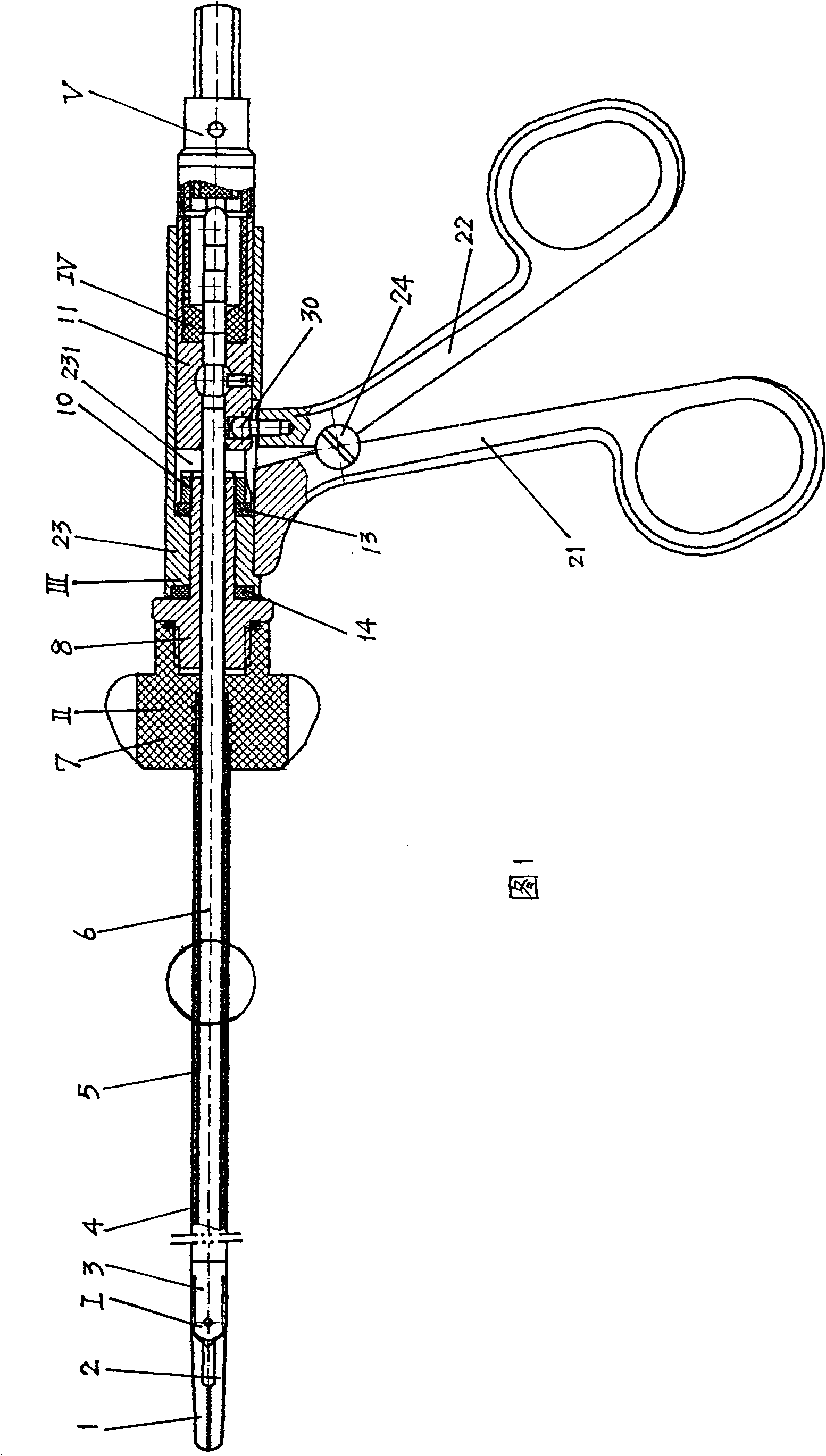
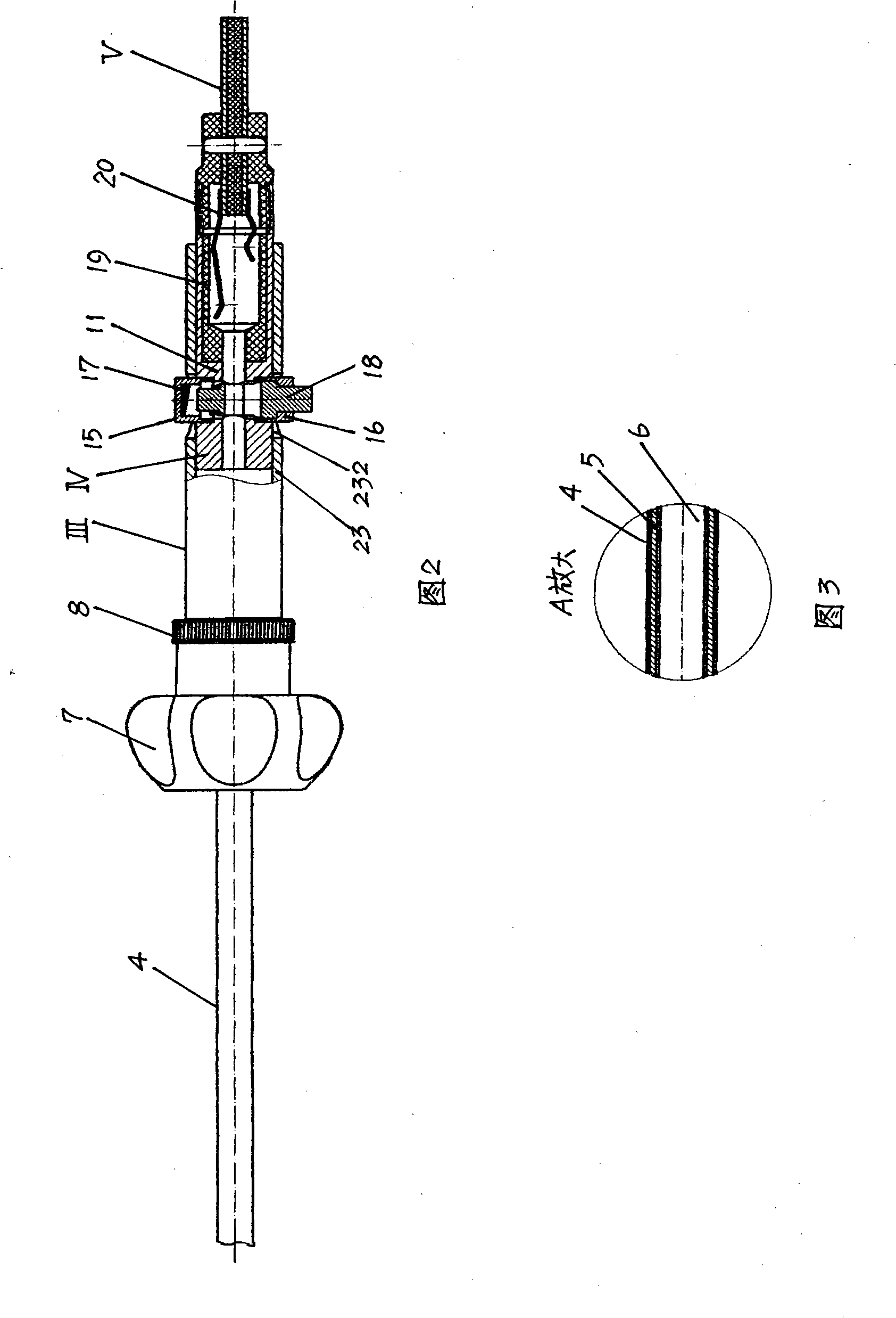
[0020] Referring to Fig. 1-Fig. 3, the present invention is mainly composed of pincer head device I, pincer tube device II, pincer handle device III, lock cylinder mechanism IV and electrode assembly V. Wherein the clamp head device I is installed on the front end of the clamp tube device II, the runner 7 at the rear end of the clamp tube device II is connected with the rotating shaft 8 in the clamp handle device III, the clamp handle device III is located at the rear end of the clamp tube device II, and the lock cylinder The mechanism IV is installed in the pincer handle device III, and the electrode assembly V is connected to the rear end of the lock cylinder mechanism IV.

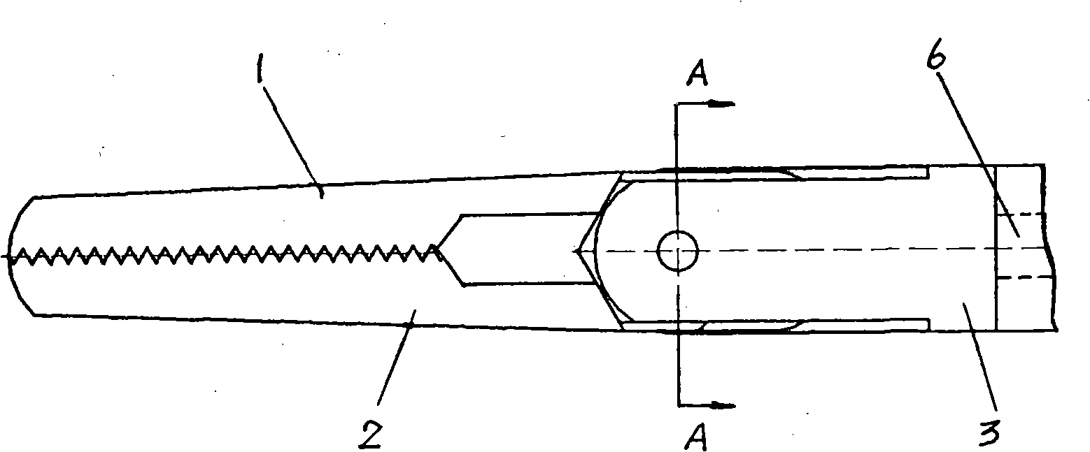
[0021] Clamp head device I comprises upper tong head 1, lower tong head 2, support frame 3 and pliers core bar 6, and upper tong head 1 and lower tong head 2 are connected with support frame 3; In the clamp tube 5, one end of the clamp core rod 6 passes through the threaded interface 281 on the support f...


PUM


Abstract

The invention relates to a medical device, in particular to a medical bipolar electric coagulation forceps. The invention is characterized in that one end of a clamp core rod in a clamp head device is connected with an external clamp tube and the other end is fixed on the main body of a lock cylinder by the lock cylinder. An insulation tube is inserted in a support frame. An axis nail is arranged in the insulation tube. An axis nail head is fixed on one end of the axis nail by welding and the other end of the axis nail is equipped with the head of the axis nail which is integrated with the axis nail into a whole. A runner on the back end of the clamp tube device is connected with a rotation axis in a clamp handle device by screw thread. The runner is fixed on the clamp tube device, and the rotation axis is arranged in the front end of the clamp handle device. A poke pin is fixed on the upper end of a back handle in the clamp handle device. The upper part of the poke pin is arranged in the main body of the lock cylinder, and an elongated slot is arranged on the main body of the handle. The medical device has the advantages of reasonable structure and design, being simple to assemble and good insulation effect, which is convenient and reliable to use.

Description

technical field [0001] The invention relates to a medical device, in particular to a medical bipolar electric coagulation forceps, which is mainly suitable for electrocoagulation blood vessel hemostasis in human body laparoscopic operation. Background technique [0002] When performing laparoscopic surgery on human body, since the diseased tissue will be removed, it is necessary to use medical bipolar electric coagulation forceps to electrocoagulate blood vessels to stop bleeding. Most of the medical electrocoagulation forceps in the prior art are monopolar forceps. During use, a negative electrode plate is generally attached to the buttocks of the human body. If the contact is poor, the skin of the human body is easily burned. The bipolar electrocoagulation forceps in the prior art includes a pincer head device, a pincer tube device, a pincer handle device, a lock cylinder mechanism and an electrode assembly, wherein the pincer head device is installed on the front end of t...

Claims


Application Information

Patent Timeline
IPC IPC(8): A61B18/04A61B1/313
Inventor 徐天松
Owner ZHEJIANG TIANSONG MEDICAL INSTR
Why Eureka
Try Eureka