Method and device for preparing microparticles by splitting liquid drop using electric charge oscillation method

An oscillation method and micro-particle technology, which is applied in the field of micro-particle preparation, can solve the problems of nozzle blockage and instability, and achieve the effects of reducing equipment investment, good product quality and short process flow.

Inactive Publication Date: 2008-10-08
TIANJIN UNIV
View PDF2 Cites 21 Cited by
  • Summary
  • Abstract
  • Description
  • Claims
  • Application Information

AI Technical Summary

Problems solved by technology

However, due to the limitation of Rayleigh jet stability conditions, the diameter of particles produced by uniform droplet injection technology is about 1.5 to 2.5 times the diameter of the nozzle. Cause nozzle clogging and jet instability

Method used


Image

  • Method and device for preparing microparticles by splitting liquid drop using electric charge oscillation method

Examples


Embodiment 1

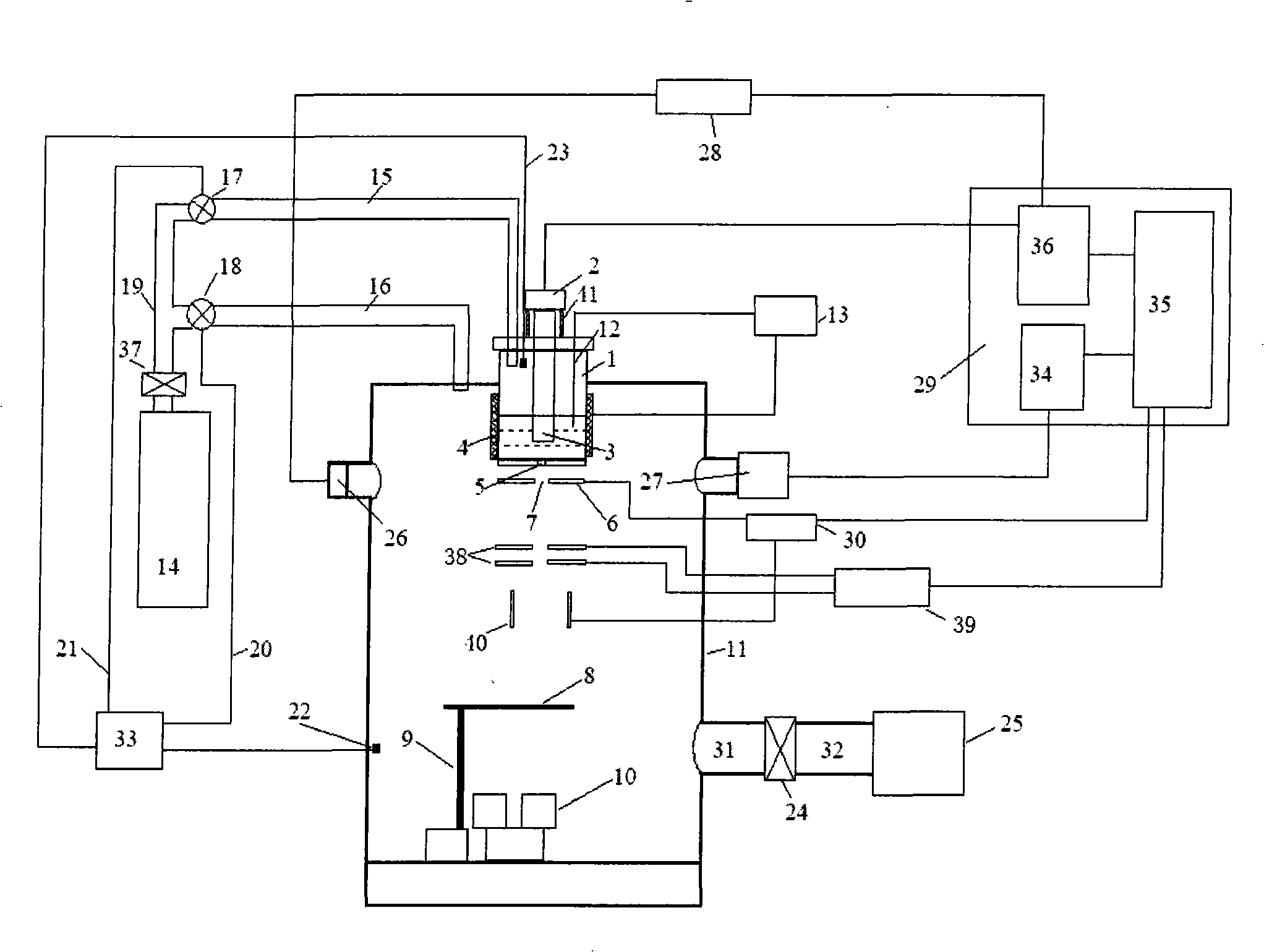
[0034] (1) Open the upper cover of the crucible, add 100g of the metal material Sn-3.5Ag-0.5Cu to be smelted into the crucible, and seal it; (2) Add the cooling liquid to the collector, and move the baffle to the top of the collector , and seal the vacuum chamber; (3) evacuate the crucible and the vacuum chamber, and fill it with nitrogen; (4) heat the crucible, melt the metal material in the crucible, and keep the temperature for 20 minutes after reaching 260 ° C; ( 5) Turn on the piezoelectric oscillator so that its frequency is 6KH Z , apply a voltage of 250V to the electrode plate, and use the pressure control system to achieve a stable pressure difference of 0.5P between the crucible and the vacuum chamber 0 , so that the molten metal is ejected from the nozzle at the bottom of the crucible in the form of a laminar jet. Under the action of the vibrating head of the piezoelectric oscillator, the outflowing metal jet breaks into uniform droplets. When passing through the ga...

Embodiment 2

[0036] (1) Open the crucible upper cover, add the metal material Sn-37%Pb 100g that needs melting in the crucible, and seal; Seal the vacuum chamber; (3) evacuate the crucible and the vacuum chamber, and fill it with nitrogen; (4) heat the crucible, melt the metal material in the crucible, and keep it warm for 25 minutes after the temperature reaches 250 ° C; (5) Turn on the piezoelectric oscillator so that its frequency is 10KH Z , apply a voltage of 200V to the electrode plate, and use the pressure control system to achieve a stable pressure difference of 1.5P between the crucible and the vacuum chamber 0 , so that the molten metal is ejected from the nozzle at the bottom of the crucible in the form of a laminar jet. Under the action of the vibrating head of the piezoelectric oscillator, the outflowing metal jet breaks into uniform droplets. When passing through the gap in the middle of the electrode plate, each Each droplet has an equal charge, the distance between the noz...

Embodiment 3

[0038] (1) Open the upper cover of the crucible, add 100g of metal material Sn-9Zn to be smelted into the crucible, and seal it; (2) Add the cooling liquid to the collector, move the baffle to the top of the collector, and seal the vacuum chamber; (3) evacuate the crucible and the vacuum chamber, and fill it with nitrogen; (4) heat the crucible, melt the metal material in the crucible, and keep it warm for 30 minutes after the temperature reaches 250 ° C; (5) open the pressure Electric oscillator makes its frequency 14.2KH Z , add a voltage of 300V to the electrode plate, and use the pressure control system to achieve a stable pressure difference of 1P between the crucible and the vacuum chamber 0 , so that the molten metal is ejected from the nozzle at the bottom of the crucible in the form of a laminar jet. Under the action of the vibrating head of the piezoelectric oscillator, the outflowing metal jet breaks into uniform droplets. When passing through the gap in the middle ...


PUM

PropertyMeasurementUnit
diameteraaaaaaaaaa
diameteraaaaaaaaaa
diameteraaaaaaaaaa

Abstract

The invention discloses a method which adopts the charge oscillometry liquid drop breakup for preparing micro-particles, and the method comprises the following steps: (1) metal material to be melted is added in a crucible; (2) cooling liquid is added in collection devices; (3) the vacuum extraction of the crucible and a vacuum cavity is carried out, and protective gas is filled; (4) the metal material in the crucible is melted; (5) a piezoelectric oscillator is opened, and the voltage is added on a charging polar plate, thus ejecting the melted metal from a nozzle at the bottom part of the crucible with the form of laminar-flow jet and respectively charging the same amount of charge to the liquid drops with two sizes when passing through the middle gap of the charging polar plate; (6) the diameter of liquid drops is calculated; (7) the evenly charged liquid drops is broken up into main liquid drops with larger size and ultra-micro-liquid drops with smaller size by the charge oscillometry on the surface of the liquid drops when passing a high-frequency alternating electric field; (8) the main liquid drops and the ultra-micro-liquid drops are fallen into the respective collection devices after the separation of a deflecting polar plate. The method of the invention has strong process controllability, which can directly obtain the even particles with more micro-size, the process flow is short, the product quality is good, and the equipment investment is greatly reduced.

Description

technical field [0001] The invention relates to the technical field of microparticle preparation, in particular to a microparticle splitting method using a charge oscillation method to split a charged droplet to obtain very small spherical particles by using a uniform droplet injection technology and a high-frequency alternating electric field to cause Coulomb splitting of the charged droplet. Methods and apparatus for particles. Background technique [0002] Chun and Passow from the Massachusetts Institute of Technology (MIT) proposed a new uniform droplet production method based on Rayleigh's capillary flow instability theory - uniform droplet ejection technology. By controlling the fracture behavior of the continuous molten metal jet, this technology can obtain spherical metal droplets or particles with uniform size. Compared with the traditional particle preparation method, it has the advantages of short process flow, good controllability, low equipment investment, high ...

Claims


Application Information

Patent Timeline
Patent Type & Authority Applications(China)
IPC IPC(8): B22F9/08
Inventor 吴萍周伟刘立娟李宝凌张洪波
Owner TIANJIN UNIV
Why Eureka
Try Eureka