Multi-source vacuum evaporation device having multi-layer radial type evaporation source distribution structure

An evaporation source and evaporation technology, applied in vacuum evaporation coating, sputtering coating, coating, etc., can solve the problems of film uniformity, shadow effect, too large chamber, etc., and achieve the reduction of vacuum chamber space , Prevent shadow effect, uniform film formation effect

Inactive Publication Date: 2008-10-08
NANJING FANGYUAN GLOBAL DISPLAY TECH
View PDF0 Cites 20 Cited by
  • Summary
  • Abstract
  • Description
  • Claims
  • Application Information

AI Technical Summary

Problems solved by technology

However, when there are multiple evaporation sources in a vacuum chamber, this technology has the following disadvantages in preparing thin films: 1) the uniformity of large-area thin films; 2) in the same vacuum chamber, the existence of multiple sources causes chamber 3) Due to the large inclination of the source relative to the orientation of the substrate, when using a mask to form a pattern, it will cause a shadow effect; 4) If there is a metal electrode source, the high-temperature evaporation of the metal will affect the same cavity Effects of organic sources at lower indoor temperatures

Method used


Image

  • Multi-source vacuum evaporation device having multi-layer radial type evaporation source distribution structure
  • Multi-source vacuum evaporation device having multi-layer radial type evaporation source distribution structure
  • Multi-source vacuum evaporation device having multi-layer radial type evaporation source distribution structure

Examples


Embodiment 1

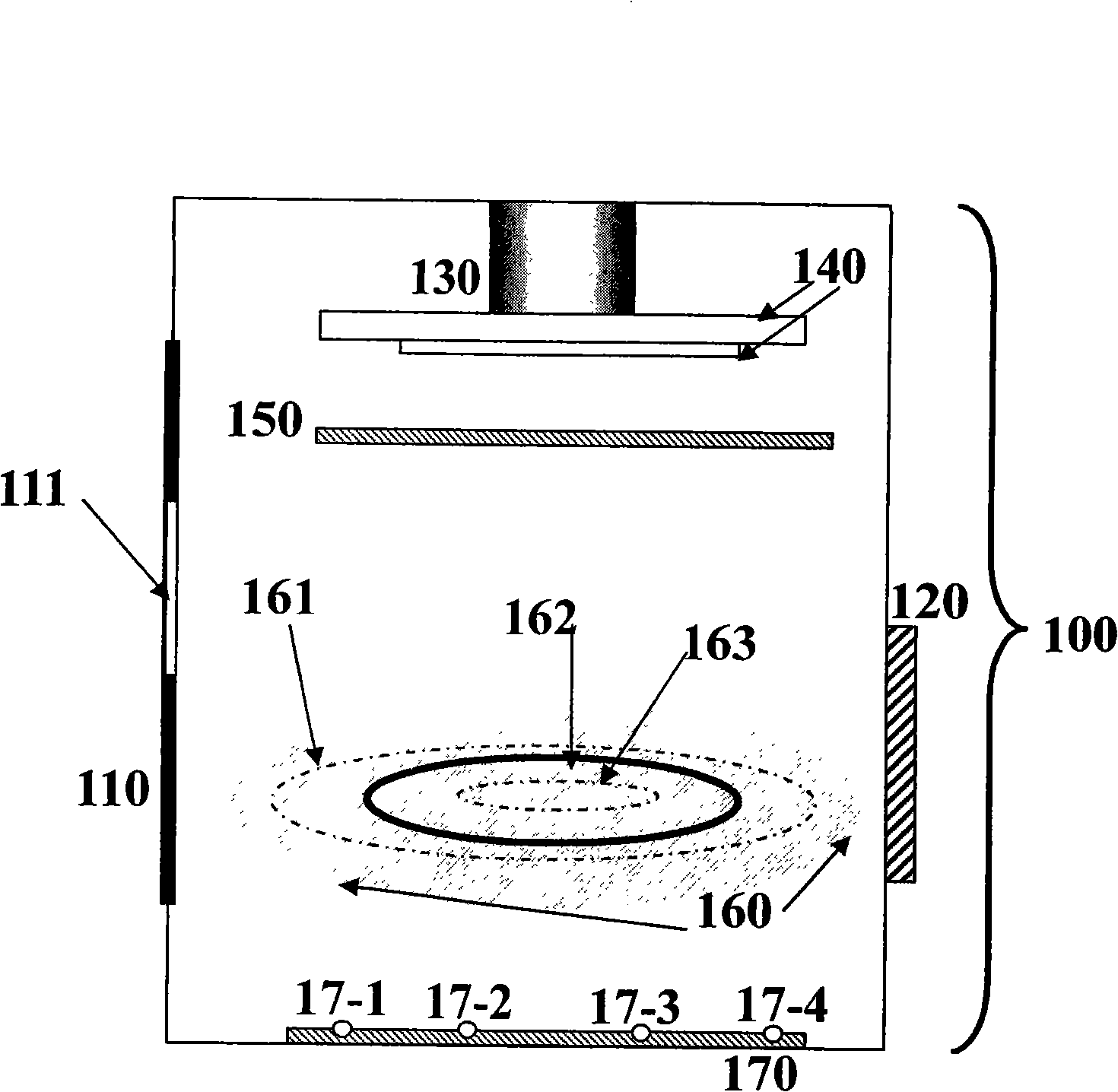
[0028] Embodiment 1 is an example of simply describing the multi-evaporation source system of this patent. exist figure 1 The shown vacuum chamber 100 has a cylindrical structure inside, with an inner diameter of 360 mm, a height of 560 mm, and a front door 110 with a size of 200 mm×350 mm. On the horizontal plane perpendicular to the central axis of the longitudinal vacuum chamber, from top to bottom, there are sample base frame horizontal plane 140 and evaporation source position horizontal plane 160, the vertical distance between sample base frame horizontal plane 140 and evaporation source position horizontal plane 160 is 300mm. The position of the evaporation source is centered on the central axis of the vacuum chamber, and in the horizontal plane 160 of the position of the evaporation source, it is divided into two layers of radial distribution: an inner ring 163 and an outer ring 161 . The positions of the evaporation sources in the outer ring 161 are distributed withi...

Embodiment 2

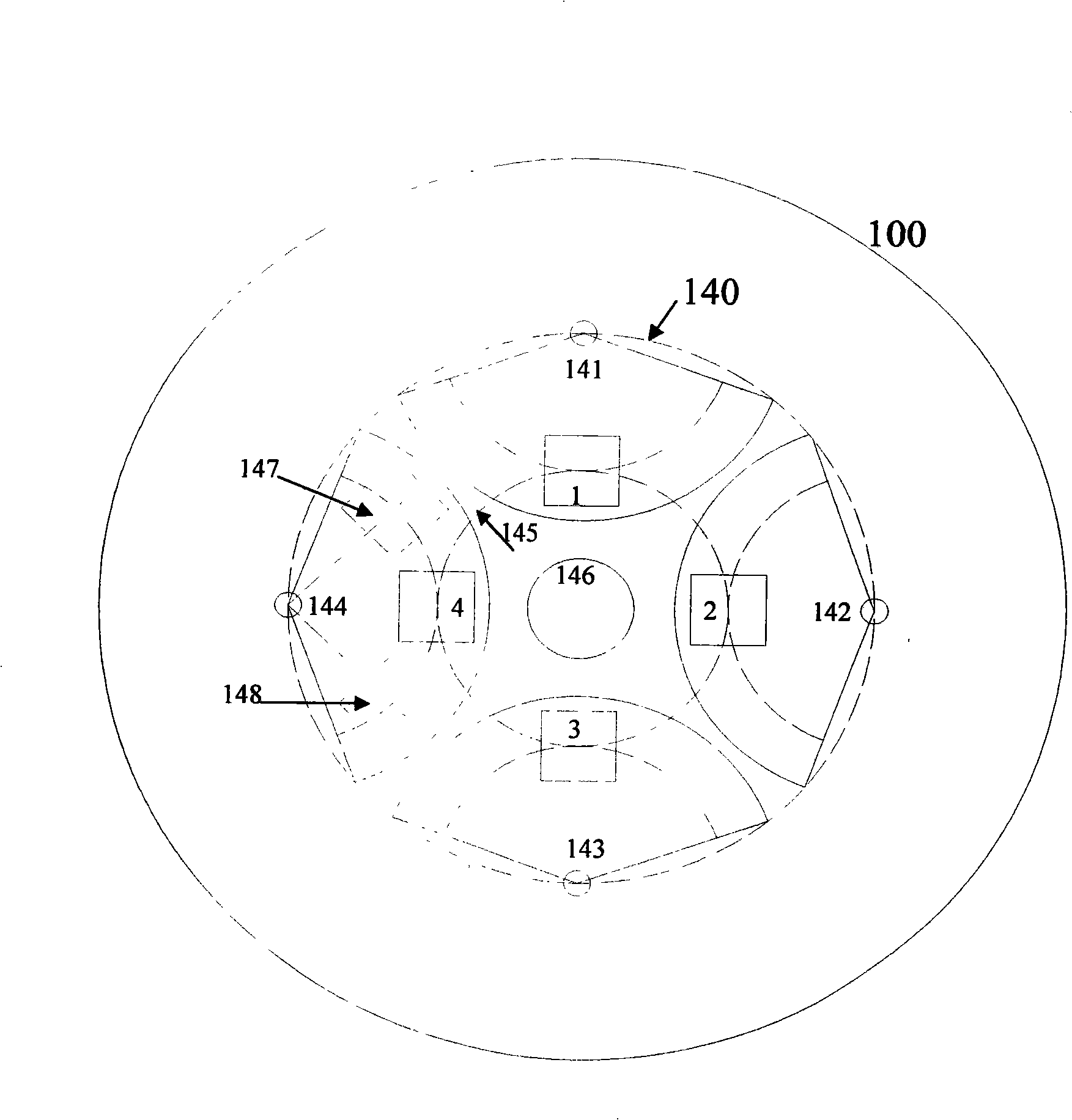
[0029] Embodiment 2 is a plan view of the horizontal plane of the sample substrate holder in the actual system. Such as figure 2 As shown, the inner diameter of the vacuum chamber 100 is 360 mm; the shapes of the first independent small baffle 141, the second independent small baffle 142, the third independent small baffle 143, and the fourth independent small baffle 144 are Fan-shaped, with a radius of 75mm, and their axes are located on a circle with a diameter of 220mm; above them, in a clockwise direction, there are sequentially distributed a first mask 147 and a second mask 148, with a size of 28mm× 28mm, and its center forms an angle of ±45° with the center line of the sector. When the small sample baffle rotates clockwise, it provides the functions of metal mask, sample baffle and organic mask in three fixed positions respectively. The centers of the first sample to be evaporated position 1, the second sample to be evaporated to position 2, the third sample to be eva...

Embodiment 3

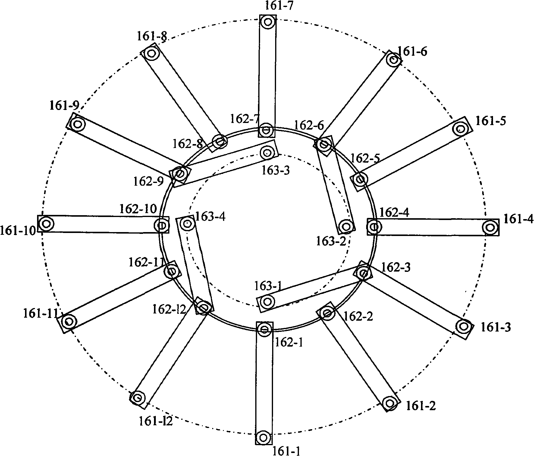
[0030] Embodiment 3, description of the horizontal plane of the evaporation source at the bottom of the vacuum chamber. Such as image 3 , 4 , 5, and 6 show the multi-layer radiation distribution of evaporation sources, the total number of evaporation sources and the number of inner layer evaporation sources are 16, 15, 14, 13, and 4, 3, 2, 1, respectively. The electrodes on the outer ring 161 are distributed on a circle with a diameter of 270 mm. By connecting with the common grounding ring 162 with a diameter of 130 mm, 12 outer layer first evaporation sources S-1 and outer layer with a diameter of 200 mm can be formed. The second evaporation source S-2, ..., the twelfth evaporation source S-12 of the outer layer; the electrodes on the inner ring 163 are distributed on a circle with a diameter of 110mm, and can form 4 by being connected with the common grounding ring 162 ( image 3 ), 3 ( Figure 4 ), 2 ( Figure 5 ), 1 ( Figure 6 ) inner layer evaporation sources, na...


PUM


Abstract

The invention relates to a multiple-source vacuum coating device of a multiple-layer radiating type evaporator source distribution structure, and an operating mode of a substrate during the filming process. The system takes a medial axle of a filming vacuum chamber as a center, and effectively arranges more evaporator sources by adopting a two-layer or multiple-layer outward radiating evaporator source distribution method on the identical horizontal plane, to satisfy the requirements of the multiple-source in the multiple-layer part structure; simultaneously, the metal evaporator source is positioned at the position approximately vertical to a coating specimen stage, to remove the shadow effect generated during the metal costing process; the rotation of the substrate during the evaporating process, and the use of an independent small baffle plate and an masking plate of each sample in the sample base frame are matched, the uniform film manufacture of the larger-sized substrate not only can be realized, the preparation of a plurality of samples and a plurality of structures in the identical vacuum process but also can be realized, and the efficiency and the comparability of the result is improved; further, the multiple-layer distributing source structure can effectively utilize the space, the volume of the volume chamber body is greatly reduced under the condition of identical evaporating amount.

Description

technical field [0001] The invention belongs to the application field of organic photoelectric thin films, and specifically relates to the structural design of a vacuum evaporation system when preparing organic photoelectric thin films under vacuum evaporation conditions. Background technique [0002] In recent years, organic optoelectronic compounds have attracted extensive attention due to their diverse types, easy modulation of properties through structural design, simple preparation and synthesis processes, and availability for flexible electronic devices. In terms of application, organic photoelectric materials are the basis of organic thin-film devices, such as organic thin-film field-effect transistors (OFETs), organic electroluminescent devices (OLEDs), organic thin-film solar cells (OPVs), organic thin-film sensors, organic lasers, etc. are inseparable from the preparation of organic thin films. [0003] In the vacuum chamber, the material to be evaporated is heate...

Claims


Application Information

Patent Timeline
Patent Type & Authority Applications(China)
IPC IPC(8): C23C14/24
Inventor 黄维密保秀高志强魏昂
Owner NANJING FANGYUAN GLOBAL DISPLAY TECH
Why Eureka
Try Eureka