

Wide span rail traffic bridge damnification detecting system
A technology for rail transit and damage detection, applied in measurement devices, special data processing applications, instruments, etc., can solve the problems of limited number of measurement points, incomplete modal data, insufficient application, etc., and achieve easy implementation and good data transmission. Features, the effect of reducing the occupancy rate
- Summary
- Abstract
- Description
- Claims
- Application Information
AI Technical Summary
Problems solved by technology
Method used
Image

Examples
Embodiment Construction
[0038] The embodiments of the present invention are described in detail below in conjunction with the accompanying drawings: this embodiment is implemented on the premise of the technical solution of the present invention, and detailed implementation methods and specific operating procedures are provided, but the protection scope of the present invention is not limited to the following the described embodiment.
[0039] This embodiment is mainly aimed at the damage detection and identification system established for long-span bridges with rail traffic, such as railways, railways and highways.
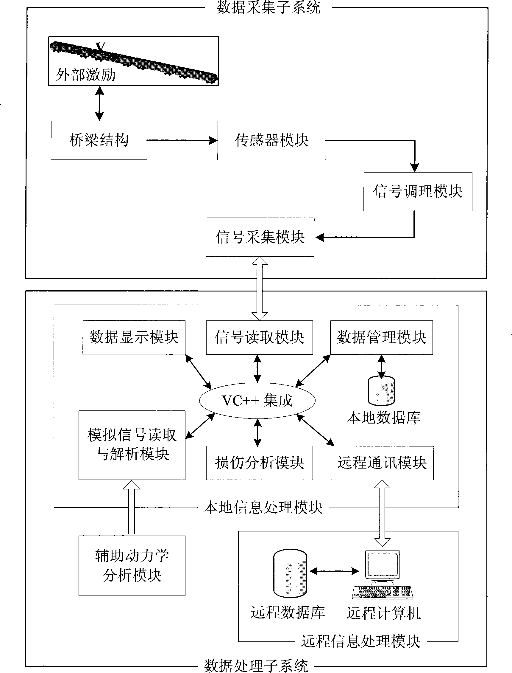
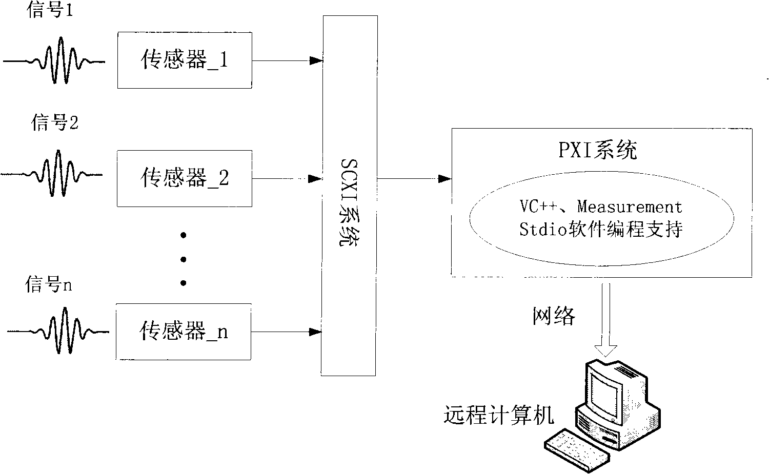
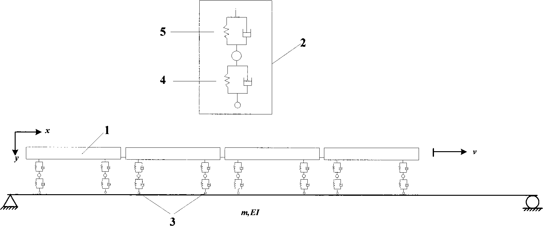
[0040] Such as figure 1As shown, this embodiment includes: two parts of the data acquisition subsystem and the data processing subsystem, wherein, the data acquisition subsystem is built as figure 2 As shown, n acceleration sensors are evenly distributed along the longitudinal central axis of the bridge, and the sensors are used to measure the acceleration of the vertical vibration of...
PUM
 Abstract
Description
Claims
Application Information