On-position type gas analysis system with on-position calibration function

A gas analysis system and analysis system technology, applied in the field of on-site gas analysis systems, can solve the problems of high processing and installation accuracy, complex devices, and low difficulty in installation and debugging, and achieve low assembly accuracy requirements, simple devices, and calibration reliable results

Active Publication Date: 2008-10-08
FOCUSED PHOTONICS
View PDF1 Cites 3 Cited by
  • Summary
  • Abstract
  • Description
  • Claims
  • Application Information

AI Technical Summary

Problems solved by technology

[0009] The invention provides an on-site gas analysis system with an on-site calibration function, which overcomes the shortcomings of the existing on-site gas analysis system with an on-site calibration function, such as complicated devices, high processing and installation precision requirements, and low difficulty in installation and debugging.

Method used


Image

  • On-position type gas analysis system with on-position calibration function
  • On-position type gas analysis system with on-position calibration function
  • On-position type gas analysis system with on-position calibration function

Examples


Embodiment

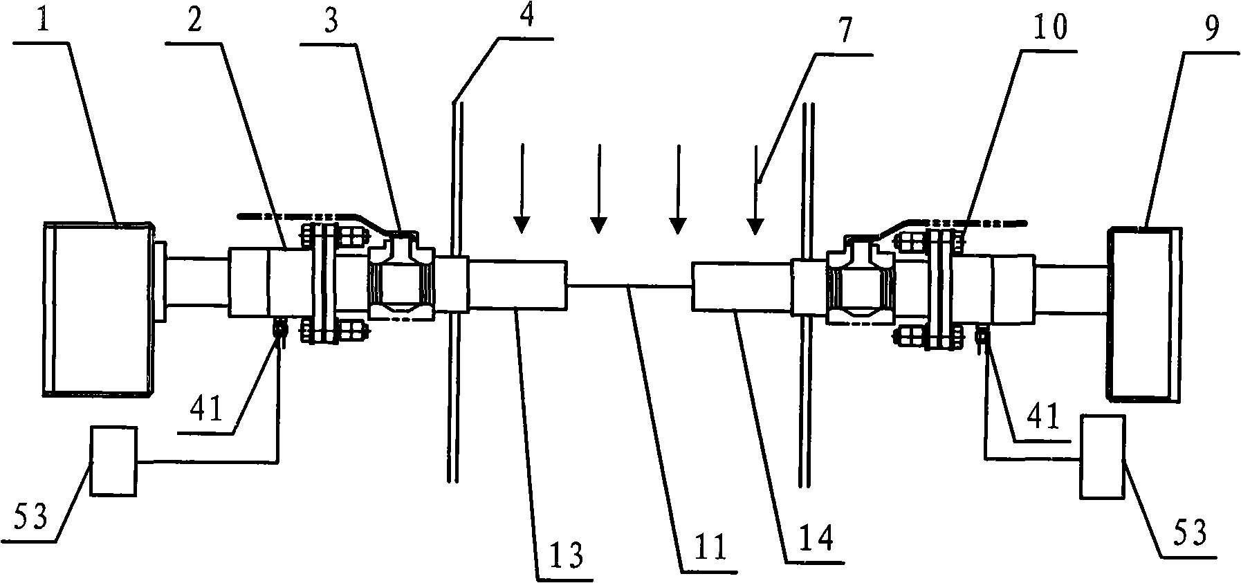
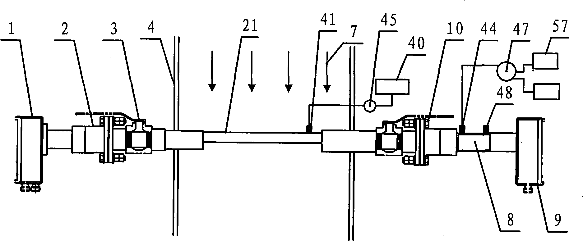
[0025] Such as figure 2 As shown, an on-site gas analysis system with an on-site calibration function is a non-dispersive infrared spectroscopy (NDIR) gas analysis system, including a light emitting device 1, a light receiving device 9, a signal analysis device, a mechanical connection structure and measuring tube. The light-emitting device 1 and the light-receiving device 9 are fitted on the measured process gas pipeline 4 through a mechanical connection structure (including a flange mating body 2 and a valve 3 ). The optical path between the light-emitting device 1 and the light-receiving device 9 can be adjusted by adjusting the bolt 10 on the mechanical connection structure to squeeze the O-ring in the middle of the flange mating body 2 . The analysis system also includes additional tubes and control means.

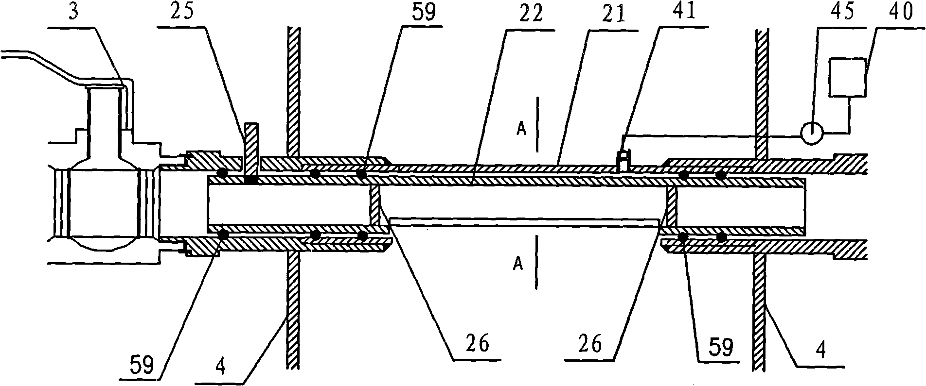
[0026] Such as image 3 As shown, the measuring tube, that is, the large C-shaped tube 21 is installed in the measured gas pipeline 4, and its two ends are connec...


PUM


Abstract

The invention discloses an in situ gas analysis system with an in situ calibration function, which includes a light emitting device, a light receiving device, a signal analysis device, a mechanical connection structure and a measuring tube, wherein, the light emitting device and the light receiving device is combined with a measured gas pipeline through the mechanical connection structure, and also includes an attached tube, a control device and a gas replacement device; the measuring tube is a big C-shaped tube whose both ends are connected with the mechanical connection structure; the attached tube is a rotatable small C-shaped tube which is arranged in the big C-shaped tube, when the small C-shaped tube rotates, the gap of the big C-shaped tube is covered, so that a closed pipeline which is isolated from the measured gas is formed in the measured gas pipeline and on a measured optical path, the gas analysis system can be in calibration or measurement situation which can be caused by adjusting the relative position of the small C-shaped tube and the big C-shaped tube; the control device is used to cause the small C-shaped tube and the big C-shaped tube to form the closed pipeline which is isolated from the measured gas, the gas replacement device comprising a gas source, a valve and a ventilation joint communicates with the closed pipeline.

Description

[0001] The patent of the present invention is a divisional application of the Chinese patent application number 2005100607797. The filing date of the original application is September 15, 2005, and the title of the invention is "an on-site gas analysis system with an on-site calibration function". technical field [0002] The invention relates to an on-site gas analysis system, in particular to an on-site gas analysis system with an on-site calibration function. Background technique [0003] The on-site gas analysis system is different from the traditional sampling method gas analysis system. It does not require sampling and pretreatment process, overcomes many defects of the traditional sampling method gas analysis system, and has the advantages of simple system, high reliability, fast measurement response speed, and analysis It has the advantages of high precision, can measure the concentration and speed of gas, and has been widely used in modern industry, scientific resear...

Claims


Application Information

Patent Timeline
Patent Type & Authority Applications(China)
IPC IPC(8): G01N21/53G01N21/31G01N21/01G01N21/27
Inventor 王健熊志才钟安平
Owner FOCUSED PHOTONICS
Why Eureka
Try Eureka