
Demodulation circuit for ultrahigh frequency radio frequency recognizing chip

A demodulation circuit and radio frequency identification technology, which is applied to the amplitude demodulation of nonlinear bipolar components, record carriers used by machines, instruments, etc., to achieve the effect of reducing chip area and cost

Inactive Publication Date: 2008-10-08
PEKING UNIV SHENZHEN GRADUATE SCHOOL
View PDF0 Cites 9 Cited by
  • Summary
  • Abstract
  • Description
  • Claims
  • Application Information

AI Technical Summary

Problems solved by technology

[0015] In view of the above background, the present invention proposes a demodulation circuit for UHF radio frequency identification chips, which can solve the problem that low power consumption and low cost cannot coexist in the prior art

Method used


Image

  • Demodulation circuit for ultrahigh frequency radio frequency recognizing chip
  • Demodulation circuit for ultrahigh frequency radio frequency recognizing chip
  • Demodulation circuit for ultrahigh frequency radio frequency recognizing chip

Examples


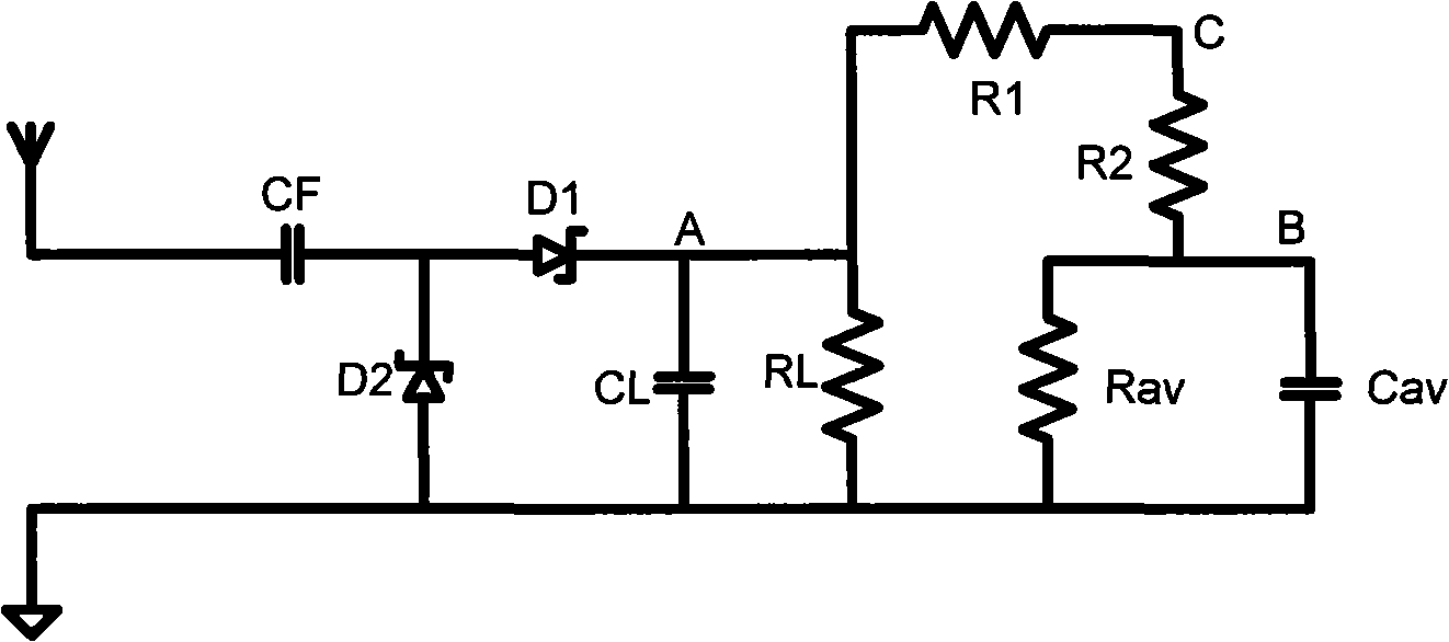
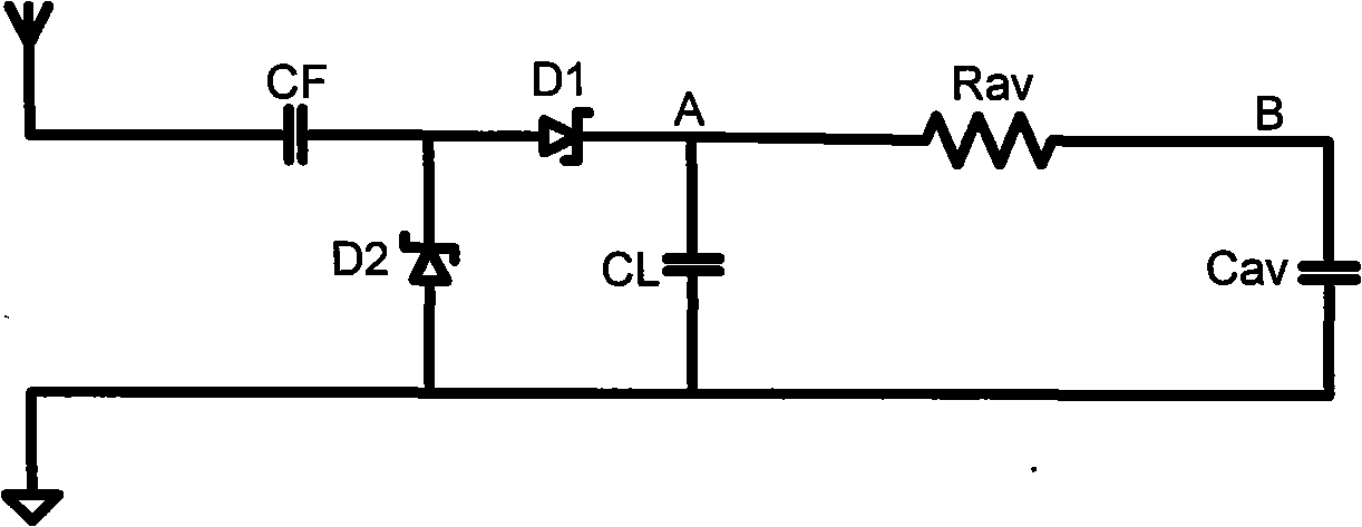
Embodiment Construction

[0027] The present invention will be described in further detail below with reference to the accompanying drawings and in combination with specific embodiments.

[0028] The demodulation circuit of Embodiment 1 of the present invention is as follows: Figure 4 As shown, its circuit structure is: it includes an envelope detection circuit and an envelope shaping circuit. The radio frequency signal received by the antenna passes through the first-stage envelope detection circuit and the second-stage envelope shaping circuit in sequence, so that the Point A and point B get the S signal and Sav signal, which are output to the comparator for demodulation. Wherein, the envelope detection circuit includes a first capacitor CF, a second capacitor CL, a first switching diode D1 and a second switching diode D2, and the radio frequency signal sequentially passes through the first capacitor CF and the first switching diode D1 to reach the signal of the envelope detection circuit Output po...


PUM


Abstract

The invention discloses a demodulator circuit used for the ultrahigh frequency radio frequency distinguishing chip, including a detecting circuit and an envelope shaping circuit, wherein the radio frequency signals received by the antenna pass through the envelope detecting circuit and the envelope shaping circuit in turn and output the S signals and the Sav signals to a comparator; the envelope shaping circuit includes a bleeder resistor, a diode, a filter resistance and a filter capacitance, wherein the bleeder resistor is connected between the signal output end of the envelope detecting circuit and the ground, the anode of the diode is connected with the signal output end of the envelope detecting circuit, while the cathode is connected with one end of the parallel branch constituted by the filter resistance and the filter capacitance, and the other end is connected with the ground, wherein the signal output end of the envelope detecting circuit is the S signal output end, while the junction of the parallel branch constituted by the filter resistance and the filter capacitance is the Sav signal output end. The invention realizes the coexistence of the low power dissipation and low cost of the demodulator circuit of the ultrahigh frequency radio frequency distinguishing chip.

Description

technical field [0001] The invention relates to a demodulation circuit for an ultra-high frequency radio frequency identification chip. Background technique [0002] UHF RFID (Ultra High Frequency Radio Frequency Identification) is a non-contact automatic identification technology, which automatically identifies the target object and obtains relevant data through radio frequency signals, without manual intervention, and can work in various harsh environments , has great advantages in fast scanning, miniaturization, anti-pollution, good durability, reusable, penetrable reading, large data memory and reliable data, and is being widely used in various industries, such as logistics and warehousing , intelligent transportation, automatic toll collection, sea and air port cargo management, supermarket retail management, medical equipment management, postal cargo tracking, etc., and also has a wide range of applications in border management, personnel safety, and sports, promoting ...

Claims


Application Information

Patent Timeline
IPC IPC(8): G06K19/077H03D1/10
Inventor 冯晓星葛彬杰王新安封君张兴
Owner PEKING UNIV SHENZHEN GRADUATE SCHOOL
Learn More