Multi-band antenna

An antenna and antenna pattern technology, applied to antennas, devices that make the antenna work in different bands at the same time, electrical components, etc., can solve the degradation of antenna gain and radiation characteristics, the limited amount of current flowing through the meandering line and the back microstrip line, etc. problems, achieving good gain and radiation characteristics, reducing wavelengths, increasing the number of effects

Inactive Publication Date: 2008-10-08
MOBITECH
View PDF0 Cites 2 Cited by
  • Summary
  • Abstract
  • Description
  • Claims
  • Application Information

AI Technical Summary

Problems solved by technology

[0014] Although the above-mentioned conventional LAN multi-strip antenna is manufactured so that such an antenna can be installed in a mobile communication terminal, the amount of current flowing through the meander line and the back microstrip line is limited, so that there is a problem that the gain and radiation characteristics of the antenna are degraded

Method used


Image

  • Multi-band antenna
  • Multi-band antenna
  • Multi-band antenna

Examples


Embodiment Construction

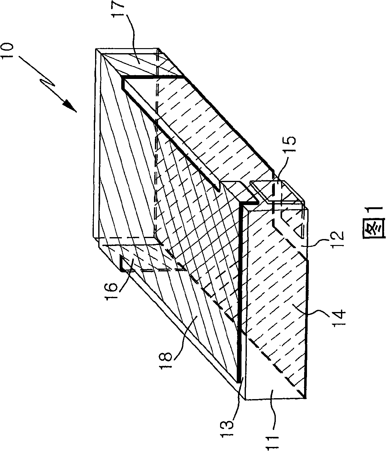
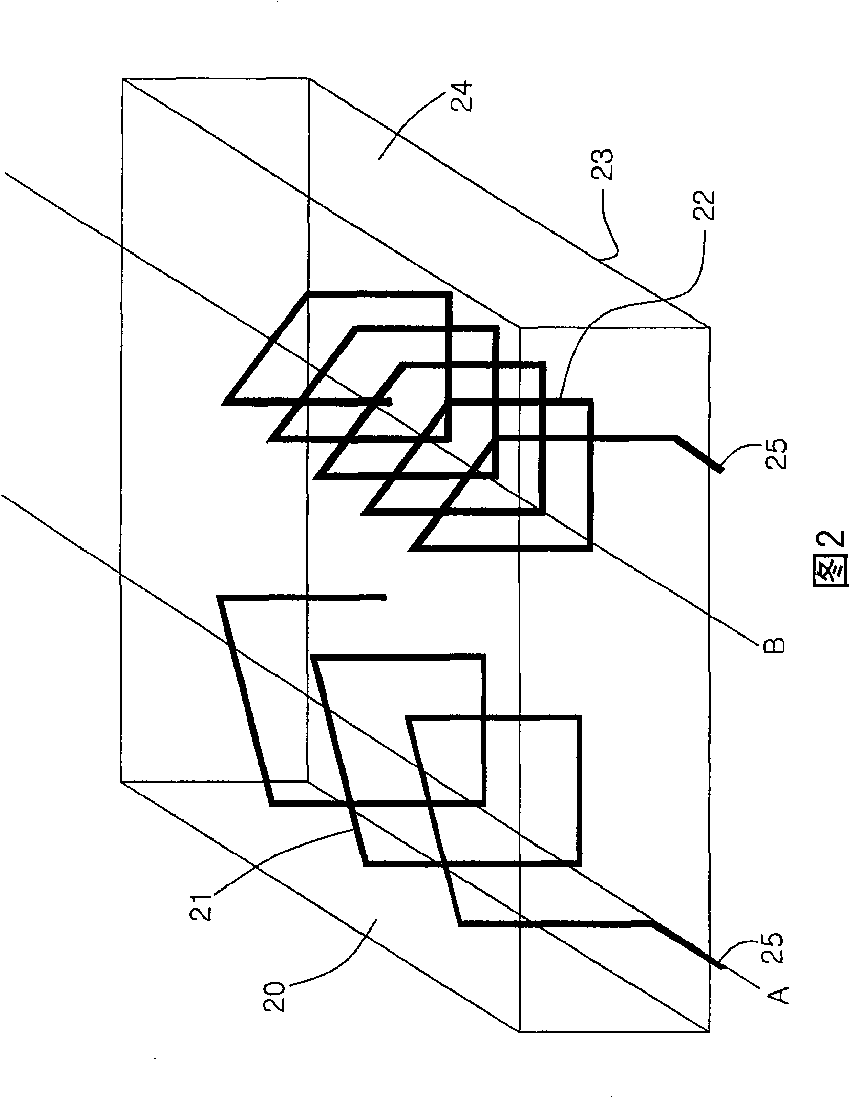
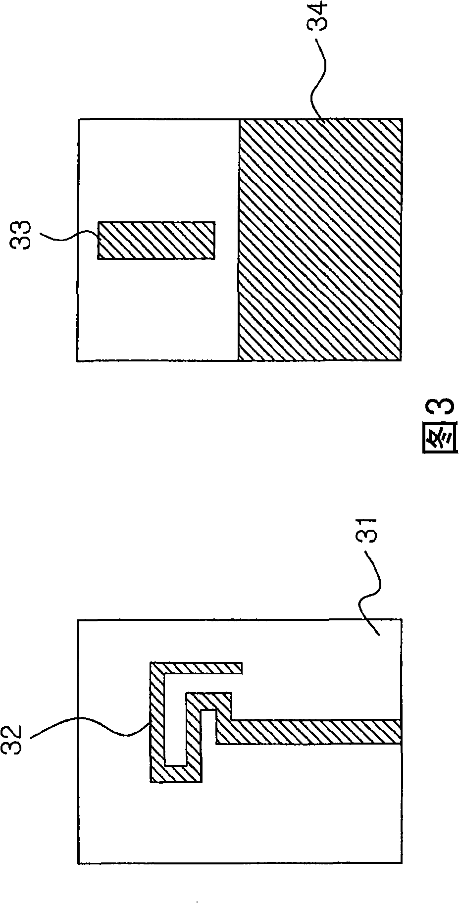
[0043] 4 is an assembled view of the first and second wires of the sub-multi-strip chip antenna 100 according to an embodiment of the present invention, and FIG. 5 is an assembled view of the conductor portion of the sub-multi-strip chip antenna 100 according to an embodiment of the present invention. .

[0044] As shown in FIGS. 4 and 5 , the sub-multiband antenna 100 includes: two through holes 110 formed parallel to each other; a fastening portion 130 configured to have a fitting recess 120 formed on the surface of the fastening portion 130 On the side facing the position between the through holes 110; the first wiring part 160 and the second wiring part are inserted into the two through holes 110 respectively; the conductive part 200 is inserted into the fitting recess 120; and the body part 180 , configured to have a recess 190 formed on one side surface of the body portion 180 so that the conduction portion 200 can be inserted into the recess 190, and the body portion 18...


PUM


Abstract

The present invention relates to a multi-band antenna and, more particularly, to a sub multi-band antenna, in which a planer conducting part, which has a plurality of protruding portions, is inserted into a depression, which is formed on the surface of a body part formed through injection molding using a mold having a specific shape to surround first and second wire members, and the fitting depression of a fastening part, which is formed through the cutting or die casting of a metal material, and to a sub-band built-in chip antenna, in which sub radiation patterns having a predetermined length are formed on the interior surface of a body part, which is formed through injection molding using a dielectric material or is formed of a layered substrate a dielectric material.

Description

technical field [0001] The present invention relates to a multi-band antenna, and more particularly, to a submulti-band antenna in which a planar-shaped conductive portion having a plurality of protrusions is inserted into a recess formed on a surface of a body portion and passed through In the fitting recess of the fastening portion formed by cutting or die-casting a metal material, the body portion is formed by injection molding using a mold having a specific shape to surround the first and second wiring members, thereby increasing the number of resonance frequency bands, And wherein the corresponding portions of the first and second wiring members protrude outside the body portion in the longitudinal direction of the body portion, thereby achieving a good radiation pattern and being usable in a plurality of resonant frequency bands, and also relates to a sub-band built-in chip antenna ( sub-band built-in chip antenna), wherein a sub-band pattern having a predetermined lengt...

Claims


Application Information

Patent Timeline
Patent Type & Authority Applications(China)
IPC IPC(8): H01Q5/00
CPCH01Q3/24H01Q5/307H01Q5/50
Inventor 吴世元李承镕
Owner MOBITECH
Why Eureka
Try Eureka