Superconductive conductor, permanent magnet and turbine composite bearing

A turbo compound and permanent magnet technology, applied in the direction of bearings, shafts and bearings, mechanical equipment, etc., can solve the problems of parts manufacturing and assembly errors, affecting running accuracy and stability, loss, etc., to improve suspension force and running rigidity , Improve the running accuracy and stability, and enhance the effect of bearing dynamic load capacity

Inactive Publication Date: 2008-10-15
刘新广
View PDF0 Cites 1 Cited by
  • Summary
  • Abstract
  • Description
  • Claims
  • Application Information

AI Technical Summary

Problems solved by technology

However, the manufacturing and assembly errors of the permanent magnet and high-temperature superconductor composite magnetic suspension bearing parts are unavoidable, the magnetic field distribution of the permanent magnet is uneven, and the high-temperature superconductor produces a magnetic pulling torque on the permanent magnet; these will affect the running accuracy and stability, so When the bearing runs at high speed, the stability cannot be high enough, and it will cause loss
And the operating rigidity of the existing permanent magnet and high temperature superconductor composite magnetic suspension bearing is not large enough

Method used


Image

  • Superconductive conductor, permanent magnet and turbine composite bearing
  • Superconductive conductor, permanent magnet and turbine composite bearing
  • Superconductive conductor, permanent magnet and turbine composite bearing

Examples


Embodiment 1

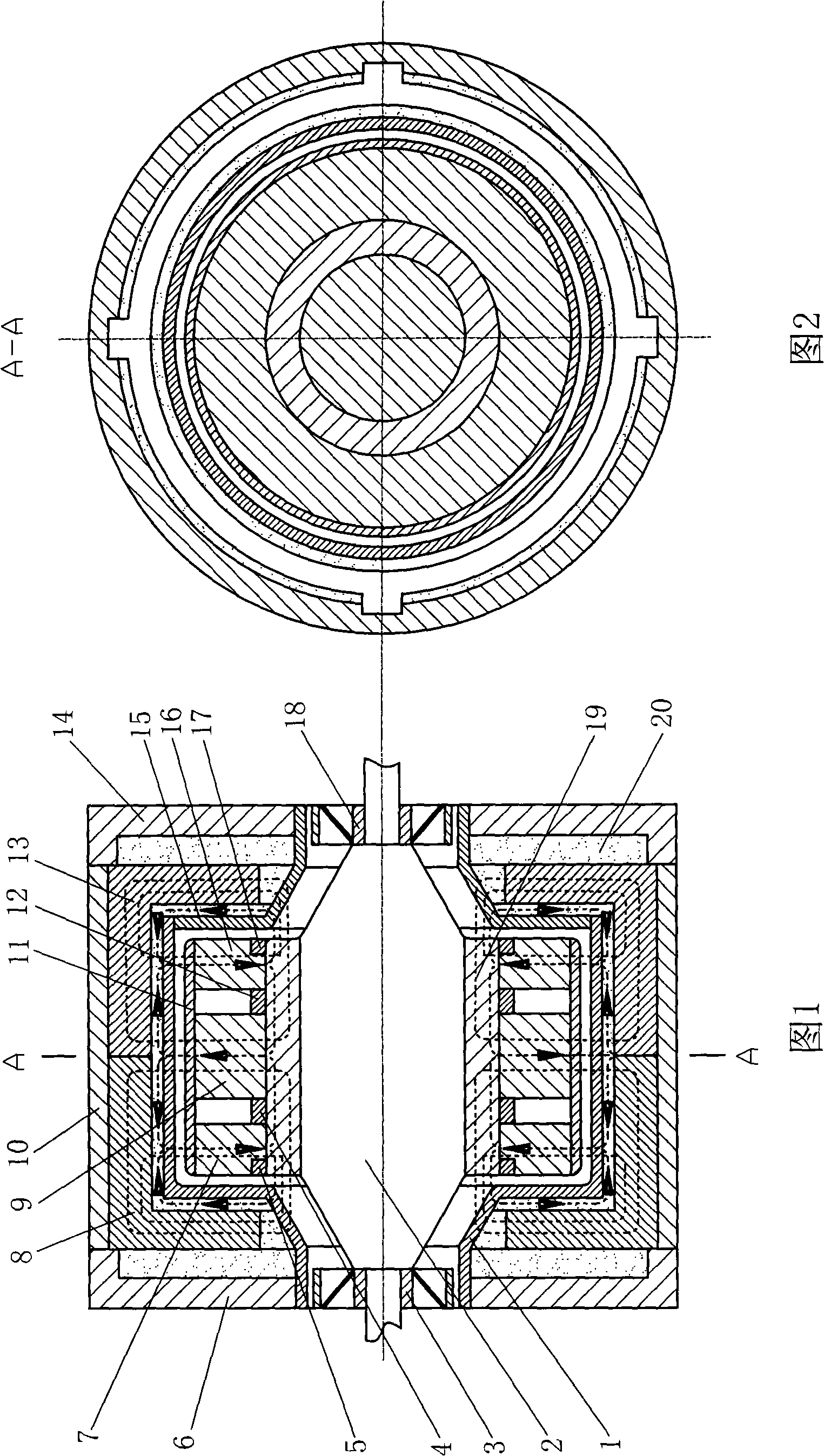
[0016] Embodiment 1: As shown in Figures 1 and 2, the bearing of this embodiment is composed of a stator and a rotor. The stator is composed of cylindrical high-temperature superconductors 8 and 13, non-magnetic insulation discs 6 and 14, non-magnetic insulation inner shells 1 and 15 and non-magnetic insulation cylinder 10-cylindrical high-temperature superconductors 8 and 13 are buttted along the axial direction. Fixed on the inner circle of the non-magnetic heat-insulating cylinder 10, and using the radial protrusions on the outer circle (shown in Figure 2) for circumferential positioning, the non-magnetic heat-insulating discs 6 and 14 are fixed on the cylindrical high-temperature superconductors 8 and 13 And the two ends of the non-magnetic heat-preserving cylinder 10, the non-magnetic heat-preserving inner shells 1 and 15 are fixed on the inner walls of the middle holes of the non-magnetic heat-preserving discs 6 and 14, respectively, and the largest outer circle of the non-m...

Embodiment 2

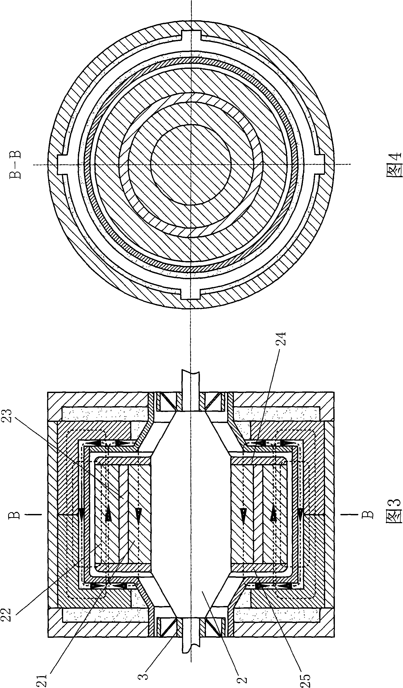
[0020] Embodiment 2: As shown in Figures 3 and 4, the bearing of this embodiment consists of a stator and a rotor. The composition of the stator is the same as that of the first embodiment. The rotor is composed of ring-shaped permanent magnets 21 and 22, non-magnetic ring 23, non-magnetic disks 24 and 25, non-magnetic shaft 2 and turbine 3 and 18 that are magnetized in the axial direction-ring-shaped permanent magnet 21 fixed sleeve On the largest outer circle of the non-magnetic rotating shaft 2, the non-magnetic ring 23 is fixedly sleeved on the outer circle of the annular permanent magnet 21, the annular permanent magnet 22 is fixedly sleeved on the outer circle of the non-magnetic annular ring 23, and the annular permanent The direction of the axial magnetic field lines in the magnet 21 is opposite to that of the annular permanent magnet 22. The non-magnetic discs 24 and 25 are also fixed on the largest outer circle of the non-magnetic rotating shaft 2, and their end faces ar...

Embodiment 3

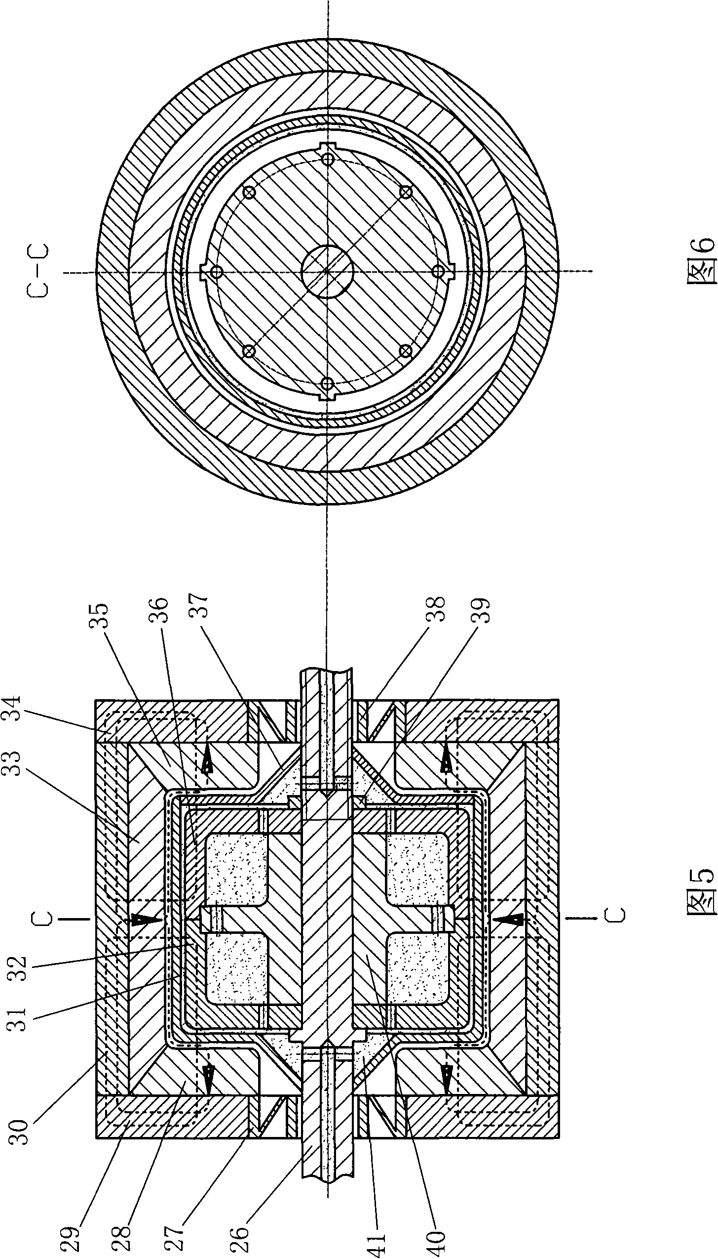
[0021] Embodiment 3: As shown in Figures 5 to 6, the bearing of the embodiment consists of a stator and a rotor. The stator is composed of a non-magnetic shaft 26, a bracket 40, cylindrical high-temperature superconductors 32 and 36, and a non-magnetic thermal insulation inner shell 31 and 37-the bracket 40, a non-magnetic thermal insulation inner shell 31 and 37 and the non-magnetic shaft 26 are solidified, non-magnetic The largest outer circle of the thermal insulation inner shell 37 is consolidated on the right end of the largest inner circle of the non-magnetic thermal insulation inner shell 31, the middle holes of the cylindrical high-temperature superconductors 32 and 36 are sleeved on the outer circle of the non-magnetic rotating shaft 26, and the cylindrical high-temperature superconductor 32 The groove of the inner cylinder wall of and 36 is caught in the protrusion of the largest outer circle of the bracket 40, so as to be circumferentially positioned. The part number 39...


PUM


Abstract

The invention provides a superconductor, a permanent magnet and a turbine composite bearing, consisting of a stator and a rotor. The stator consists of a cylinder-shaped high temperature superconductor and a refrigerant chamber component, wherein the high temperature superconductor is placed in refrigerant and fixed by the chamber component; the rotor consists of circular ring(cylinder)-shaped permanent magnets which are magnetized along the radial direction and the axial direction respectively, a non-magnetic circular ring, a non-magnetic disk, a circular ring-shaped magnetizer, a non-magnetic rotating shaft and turbines. The stator high temperature superconductor rejects the majority of magnetic force lines emitted by the rotor permanent magnet to the utmost and simultaneously pins a small part of magnetic force lines, which makes the rotor be suspended; the turbines arranged on both ends of the rotor turn in a high speed along with the rotor and spin environmental fluids in clearances between the rotor and the stator, forming a high pressure air cushion or a static liquid layer, thereby effectively limiting the unstable operation of the bearing, improving the suspension force and the operational rigidity of the bearing, further improving operational accuracy and stability and enhancing the dynamic loading capacity of the bearing, so as to meet the requirement of high-accuracy equipment.

Description

Technical field [0001] The invention relates to a suspension bearing, in particular to a superconductor, permanent magnet and turbo compound suspension bearing. Background technique [0002] The rotating sleeve and the fixed sleeve of the magnetic suspension bearing are relatively suspended by magnetic force, so there is no wear, no noise, no pollution, no transmission of vibration, no lubrication, and long life. [0003] Magnetic suspension bearings have electromagnetic type, permanent magnet type, electromagnetic permanent magnet combined type, permanent magnet and high temperature superconductor composite type. In comparison, the permanent magnet suspension bearing has a simple structure and low cost, but its operation accuracy and stability are poor, and its application is greatly restricted. Electromagnetic uses the magnetic force generated by the current to make the inner sleeve and outer sleeve of the bearing relatively suspended. A complex circuit control system must be c...

Claims


Application Information

Patent Timeline
Patent Type & Authority Applications(China)
IPC IPC(8): F16C32/00
Inventor 刘新广
Owner 刘新广
Why Eureka
Try Eureka