Separable detecting viewfinder and detecting system
A separation type, window technology, applied in the field of detection devices of the plasma process, can solve the problems of uneven bottom surface of the detection window, difficult to clean, and high replacement cost, so as to solve the problem of unclean cleaning, reduce process costs, and solve cleaning problems. difficult effect
- Summary
- Abstract
- Description
- Claims
- Application Information
AI Technical Summary
Problems solved by technology
Method used
Image


Examples
no. 1 example
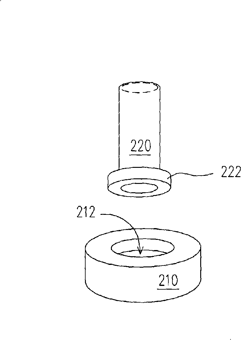
[0040] figure 2 It is an exploded perspective view of the detachable detection window according to the first embodiment of the present invention.
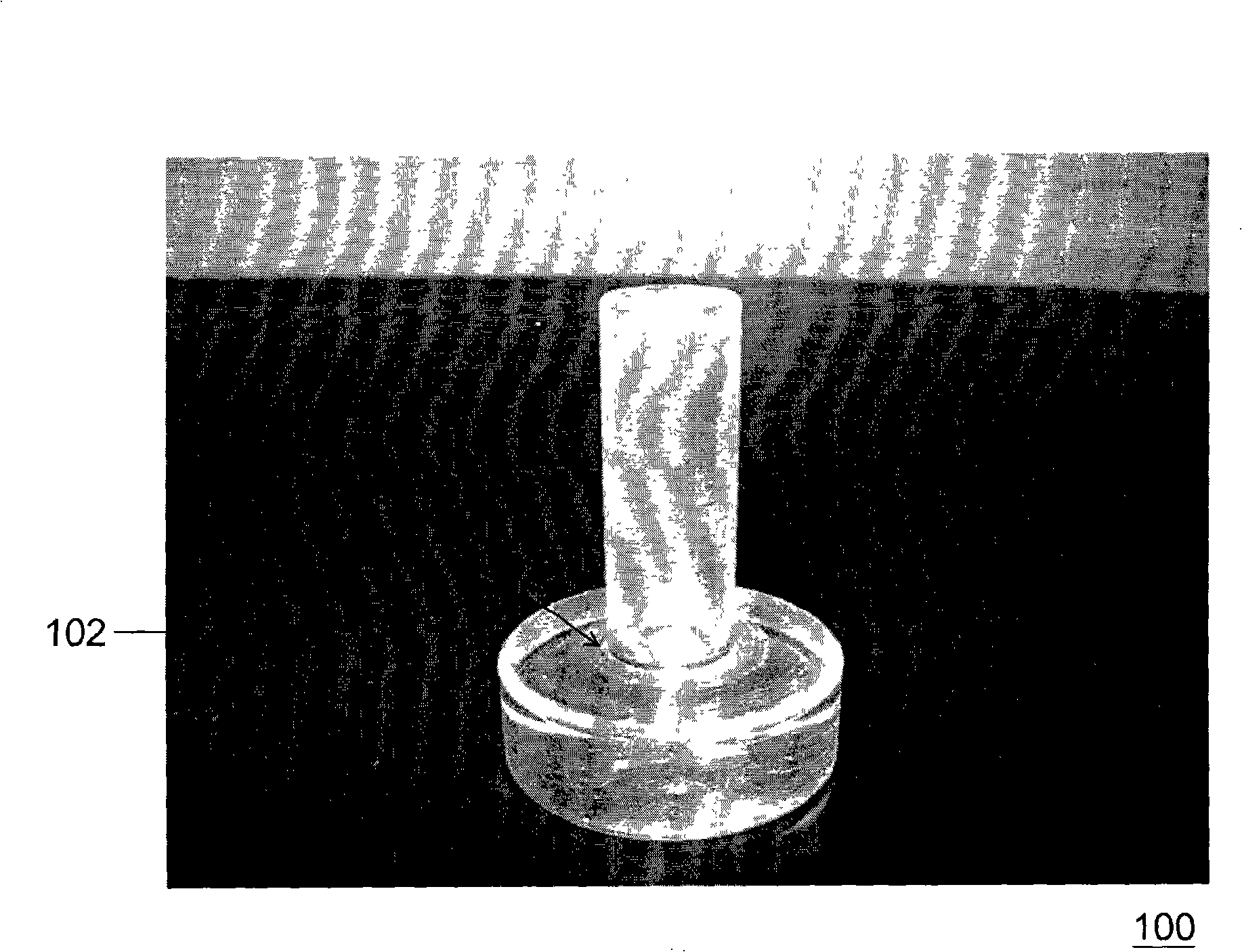
[0041] Please refer to figure 2 , the detachable detection window of this embodiment mainly includes a base 210 and a hollow pipe 220 . Wherein, the base 210 has a first combining portion 212 , and the first combining portion 212 is, for example, a concave portion. The base 210 is made of a transparent material, such as glass, quartz, acrylic or other suitable transparent materials. In addition, one end of the hollow tube 220 has a second joint portion 222 , such as a protrusion corresponding to the first joint portion 212 . The material of the hollow tube 220 may be the same as or different from that of the base 210 . The material of the hollow tube 220 is a transparent material, such as glass, quartz, acrylic or other suitable transparent materials.
[0042] The present invention does not specifically limit the shapes of t...
no. 2 example
[0049] Figure 6 It is an exploded perspective view of the detachable detection window according to the second embodiment of the present invention.
[0050] Please refer to Figure 6 , the detachable detection window of this embodiment is similar to the detachable detection window of the first embodiment, the main difference is only: the base 610 and the hollow pipe 620 of the detachable detection window of this embodiment are provided with threads The groove is formed by using a locking method.
[0051] The base 610 of the detachable detection window of this embodiment has a first joint portion 612 . The first coupling portion 612 is, for example, a concave portion, and a thread groove is provided on an inner peripheral surface of the concave portion. The base 610 is made of a transparent material, such as glass, quartz, acrylic or other suitable transparent materials. One end of the hollow pipe 620 has a second joint portion 622 , and the second joint portion 622 is prov...
no. 3 example
[0055] Figure 8 It is an exploded perspective view of the detachable detection window according to the third embodiment of the present invention.
[0056] Please refer to Figure 8 , the detachable detection window of this embodiment mainly includes a base 810 and a hollow pipe 820 . Wherein, the base 810 has a first combining portion 812 , for example, the first combining portion 812 is a concave portion formed by bending a part of the base 810 inward. The base 810 is made of a transparent material, such as glass, quartz, acrylic or other suitable transparent materials. In addition, one end of the hollow tube 820 has a second joint portion 822 , and the second joint portion 822 is inserted into the first joint portion and rotated by an angle, so that the first joint portion 812 and the second joint portion 822 will engage. The material of the hollow tube 820 can be the same as or different from that of the base 810 . The material of the hollow tube 820 is a transparent m...
PUM
 Abstract
Description
Claims
Application Information
 - R&D
- Intellectual Property
- Life Sciences
- Materials
- Tech Scout
- Unparalleled Data Quality
- Higher Quality Content
- 60% Fewer Hallucinations
Browse by: Latest US Patents, China's latest patents, Technical Efficacy Thesaurus, Application Domain, Technology Topic, Popular Technical Reports.
© 2025 PatSnap. All rights reserved.Legal|Privacy policy|Modern Slavery Act Transparency Statement|Sitemap|About US| Contact US: help@patsnap.com