Near infrared ray reflective substrate and near infrared ray reflective laminated glass employing that substrate, near infrared ray reflective double layer glass
A near-infrared, reflective substrate technology, applied in windshields, transportation and packaging, instruments, etc., can solve problems such as difficult to use conductive films
- Summary
- Abstract
- Description
- Claims
- Application Information
AI Technical Summary
Problems solved by technology
Method used
Image

Examples
example 1
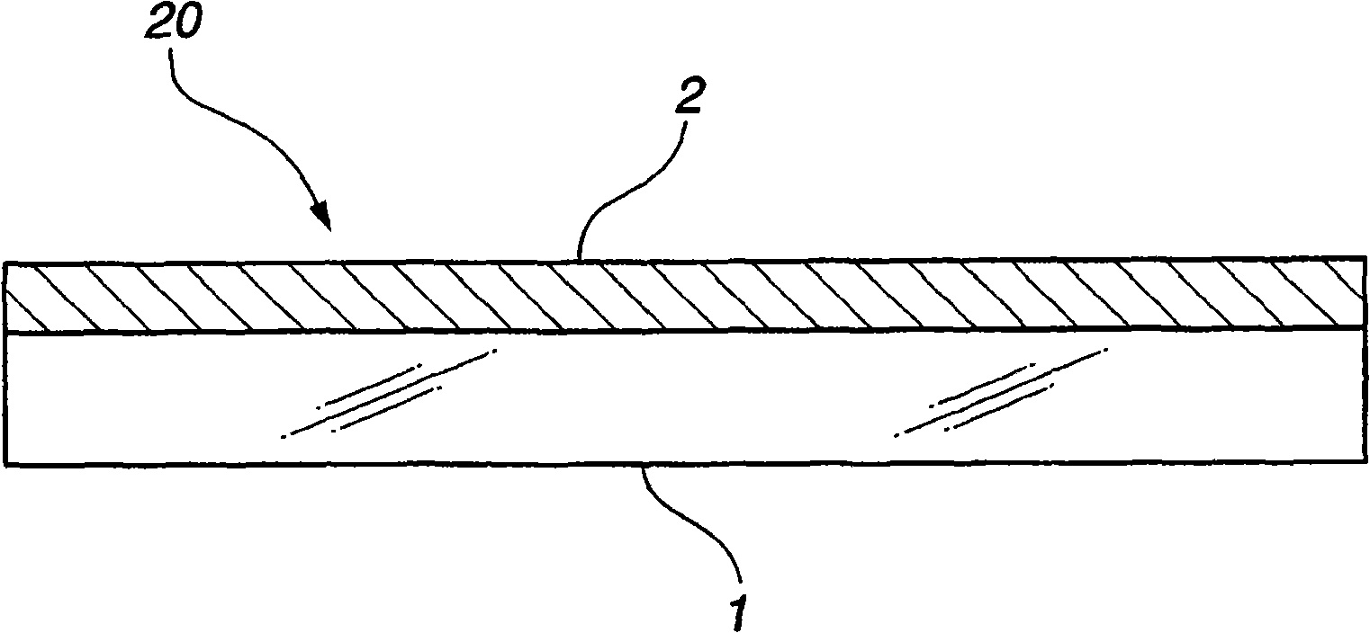
[0066] The near-infrared reflection substrate 20 shown in FIG. 1 was formed. As the transparent substrate 1 , a sheet glass 3 (see FIG. 2 ) of transparent soda-lime glass produced by a float process having a size of 1000 mm×1000 mm and a thickness of 2 mm was used.
[0067] The plate glass was washed and dried and placed in a sputtering film forming apparatus. Five layers of dielectric films were deposited on the surface to form the near-infrared reflection film 2 .
[0068] By film formation in this order from the glass surface TiO2 film (thickness: 105nm), SiO2 film (thickness: 175nm), TiO2 film (thickness: 105nm), SiO2 film (thickness: 175nm) and TiO2 film (thickness: 105 nm) to form a dielectric film constituting the near-infrared reflection film 2 . The resistance of the dielectric film stack was measured and it was almost infinite.
[0069] The visible light transmittance defined by JISR3106-1998 of the near-infrared reflective substrate was 83%. When examining the refle...
example 2
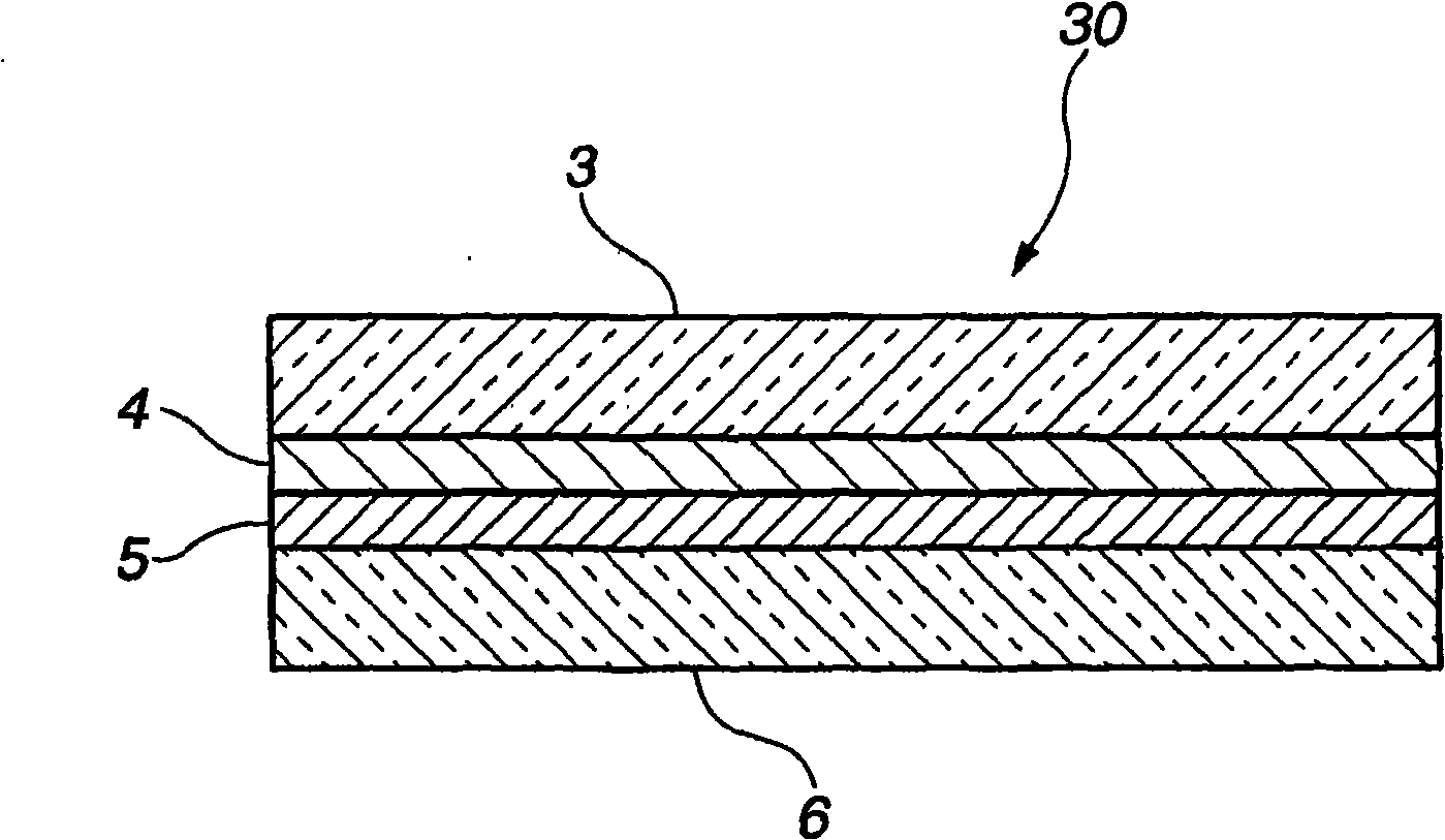
[0070] Using the near-infrared reflective substrate 20 formed in Example 1, the near-infrared reflective laminated glass shown in FIG. 2 was produced.
[0071] The near-infrared reflection film 4 is positioned on one side of the interlayer film 5. As the interlayer film 5, a PVB film having a thickness of 0.76 mm was used.
[0072] As the sheet glass 6, the same sheet glass as the sheet glass 3 used in Example 1 was used.
The near-infrared reflective substrate 20 (that is, the lamination of plate glass 3 and near-infrared reflective film 4 among Fig. 2 ), interlayer film 5 and plate glass 6 laminated together made in example 1, then Pressing / heating treatment was performed to produce a near-infrared reflective laminated glass 30 in which the near-infrared reflective substrate 20 produced in Example 1 and the sheet glass 6 were bonded together through the interlayer film 5 .
[0074] The visible light transmittance defined by JIS R3106-1998 of the near-infrared reflective lamina...
example 3
[0076] A near-infrared reflective substrate 20 shown in FIG. 1 was formed in the same manner as in Example 1 except that the near-infrared reflective film 2 was formed by a seven-layer dielectric film.
By pressing Nb2O5 film (thickness: 115nm), SiO2 film (thickness: 175nm), Nb2O5 film (thickness: 115nm), SiO2 film (thickness: 175nm), Nb2O5 film (thickness: 175nm) on the glass surface of sheet glass 1, Nb2O5 film (thickness: : 115nm), a SiO2 film (thickness: 175nm) and a Nb2O5 film (thickness: 115nm) of seven layers of dielectric film deposited in this order constitute the near-infrared reflective film 2 .
[0078] By measuring the resistance of the 7-layer dielectric film, it was confirmed that it was almost infinite, and there was no problem in propagation of electromagnetic waves, similar to Example 1.
[0079] The visible light transmittance defined by JISR3106-1998 of the near-infrared reflective substrate was 81%. When examining the reflective properties of the surface of ...
PUM
| Property | Measurement | Unit |
|---|---|---|
| thickness | aaaaa | aaaaa |
| thickness | aaaaa | aaaaa |
| thickness | aaaaa | aaaaa |
Abstract
Description
Claims
Application Information
 - R&D
- Intellectual Property
- Life Sciences
- Materials
- Tech Scout
- Unparalleled Data Quality
- Higher Quality Content
- 60% Fewer Hallucinations
Browse by: Latest US Patents, China's latest patents, Technical Efficacy Thesaurus, Application Domain, Technology Topic, Popular Technical Reports.
© 2025 PatSnap. All rights reserved.Legal|Privacy policy|Modern Slavery Act Transparency Statement|Sitemap|About US| Contact US: help@patsnap.com