Layer-by-layer speed regulating device for spinning frame

A technology of speed control device and servo motor, applied in textiles and papermaking, etc., can solve the problem of inability to achieve the effect, does not solve the change of the tension of the lifting balloon, does not consider the change of the winding radius of the ring plate and the change of the height of the balloon, etc. question

Inactive Publication Date: 2008-10-22
JINGWEI TEXTILE MASCH CO LTD
View PDF0 Cites 24 Cited by
  • Summary
  • Abstract
  • Description
  • Claims
  • Application Information

AI Technical Summary

Problems solved by technology

[0006] The above two speed regulation methods only consider the simple speed regulation by dividing the height of the balloon into several stages during spinning and doffing, but do not consider the change of the winding radius and the he

Method used


Image

  • Layer-by-layer speed regulating device for spinning frame
  • Layer-by-layer speed regulating device for spinning frame
  • Layer-by-layer speed regulating device for spinning frame

Examples


Embodiment Construction

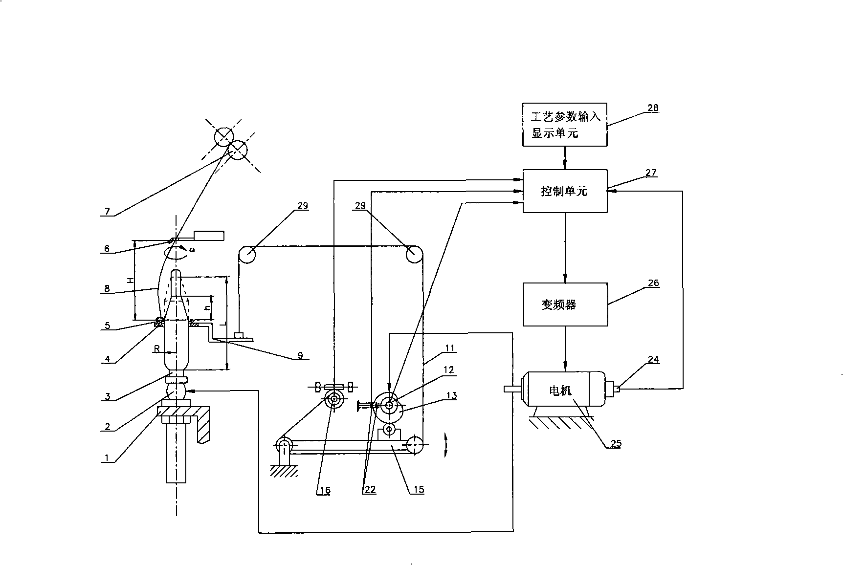
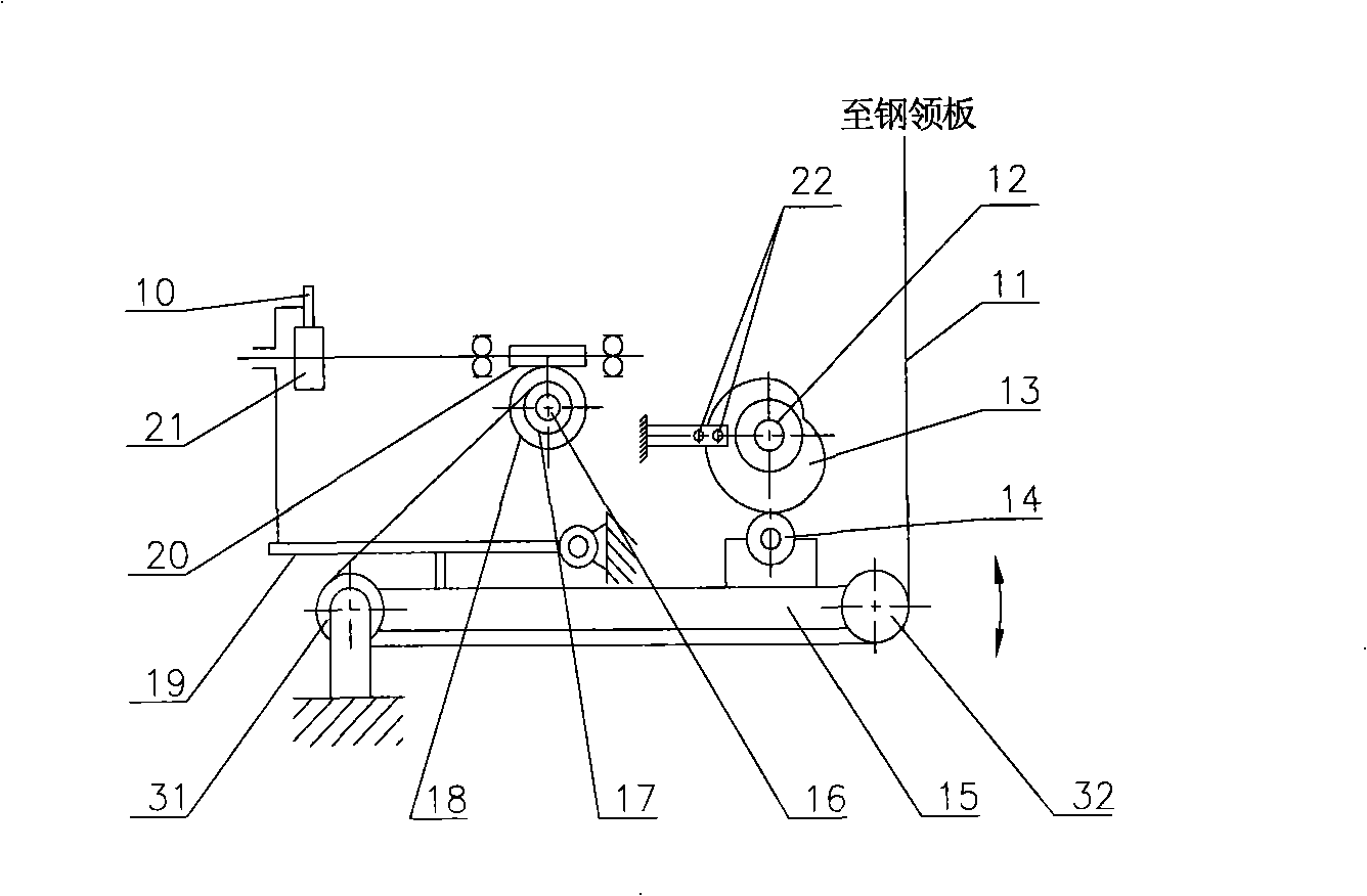
[0034] The invention adopts forming cam, lifting swing arm, traction chain, steel ring plate, ratchet pawl step-up mechanism, winding sprocket, control unit, display input unit, frequency converter, motor, encoder or sensor to form spinning frame Layer speed control device. According to different winding radii and balloon heights, the running speed of the spindle is changed, and constant tension spinning is realized by layer-by-layer speed regulation.

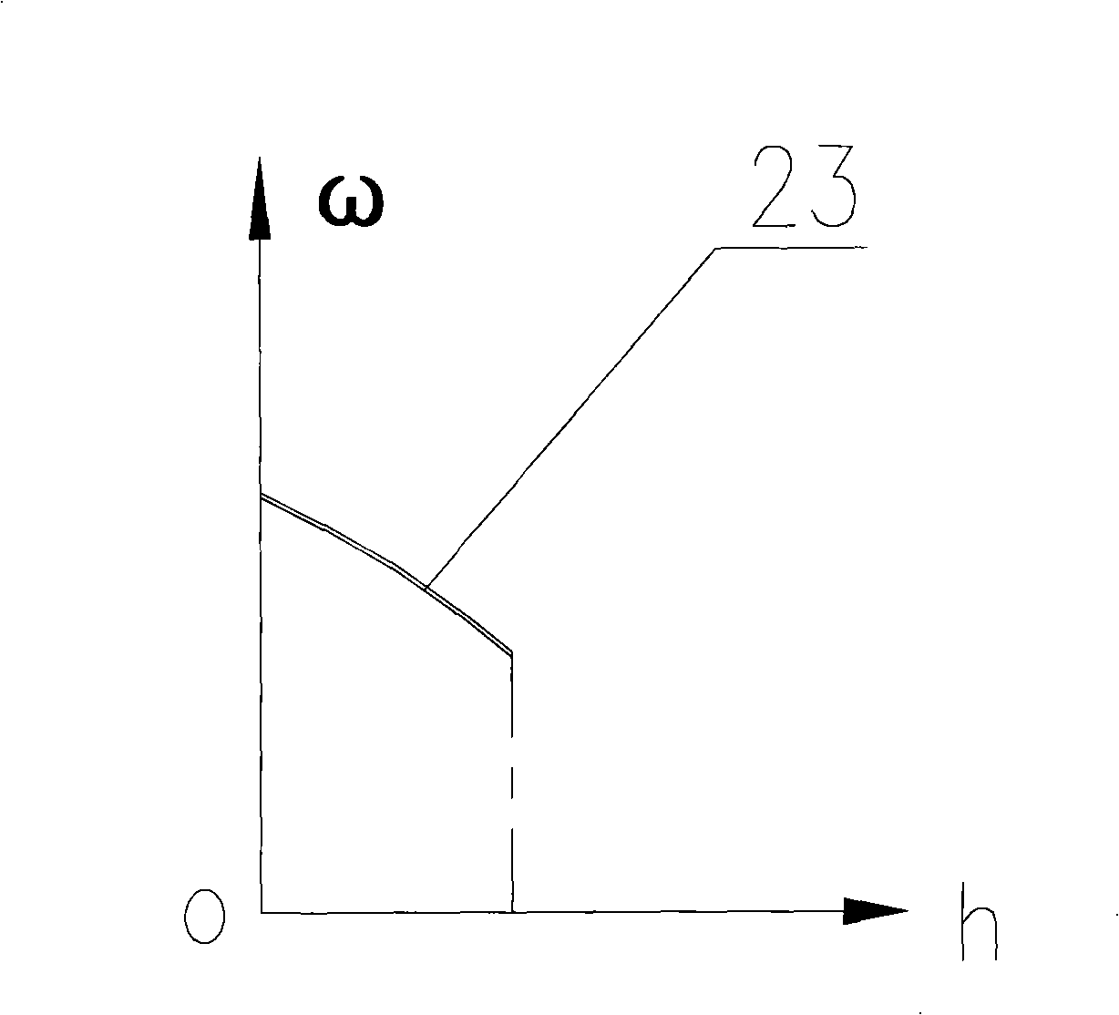
[0035] Firstly, input the spinning variety and process parameters into the display unit, and the control unit bases on the input parameters, the short stroke position of the ring plate lifting given by the forming cam encoder, and the step-up position of the ring plate given by the winding sprocket encoder , and according to the speed regulation curve 23 obtained by experiments or calculations, the control unit sends a control command to the frequency converter through calculation, and the frequency converter sends a frequency ...


PUM


Abstract

The invention relates to a layer-by-layer speed governing spinning device for a spinning machine. The invention comprises a forming cam, a lifting oscillating arm, a lifting chain, a ring bar, a ratchet wheel cascade ascent mechanism, a winding chain wheel, a control unit, a display input unit, a transducer, an electric motor, a sensory control unit, a display screen, a transducer, an electric motor, encoders and so on, wherein, the encoders are arranged on the forming cam, the winding chain wheel and the electric motors; a speed governing curve according to set spinning tensile forces can be obtained by input of set spinning varieties and technological parameters through the display screen, and constant-tension spinning is realized. The layer-by-layer speed governing spinning device reduces broken ends for spinning, reduces the amount of labor, improves the output and increases the economic benefit.

Description

technical field [0001] The patent of the present invention relates to the field of textile machinery, in particular to a layer-by-layer speed regulating device used on a spinning frame and a spinning frame using the layer-by-layer speed regulating device. The device can realize constant tension spinning, reduce the yarn breakage rate and increase the output. Background technique [0002] The spinning speed of the existing ring spinning frame is mainly restricted by the broken end of the spun yarn. Spinning end breakage is the most important hazard in spinning production, which directly affects spinning quality, output and production efficiency. Reducing end-break rate is the key to spinning frame production. The main factor of spun yarn breakage is that the tension value of the balloon momentarily exceeds the cohesion strength value of the yarn. The increase of spinning speed is mainly restrained by the tension of spinning balloon. The change of the balloon tension of th...

Claims


Application Information

Patent Timeline
IPC IPC(8): D01H13/00D01H13/10
Inventor 金光成蔺建旺张新民唐海丽江玮孟鑫
Owner JINGWEI TEXTILE MASCH CO LTD
Why Eureka
Try Eureka