

Process for making continuous grooves underground by rotating drill and device thereof
A trench and auger technology, which is applied to excavation, sheet pile walls, earth movers/shovels, etc., can solve the problems of high cost, heavy pollution, complicated process, etc., and achieve simple installation, good environmental protection, and joint effect Good results
Inactive Publication Date: 2008-10-22
王英权
View PDF0 Cites 4 Cited by
- Summary
- Abstract
- Description
- Claims
- Application Information
AI Technical Summary
Problems solved by technology
Large pollution, time-consuming, complex process, high cost
Method used
View moreImage
Smart ImageViewing Examples

Examples
Embodiment Construction
Login to View More PUM
 Abstract
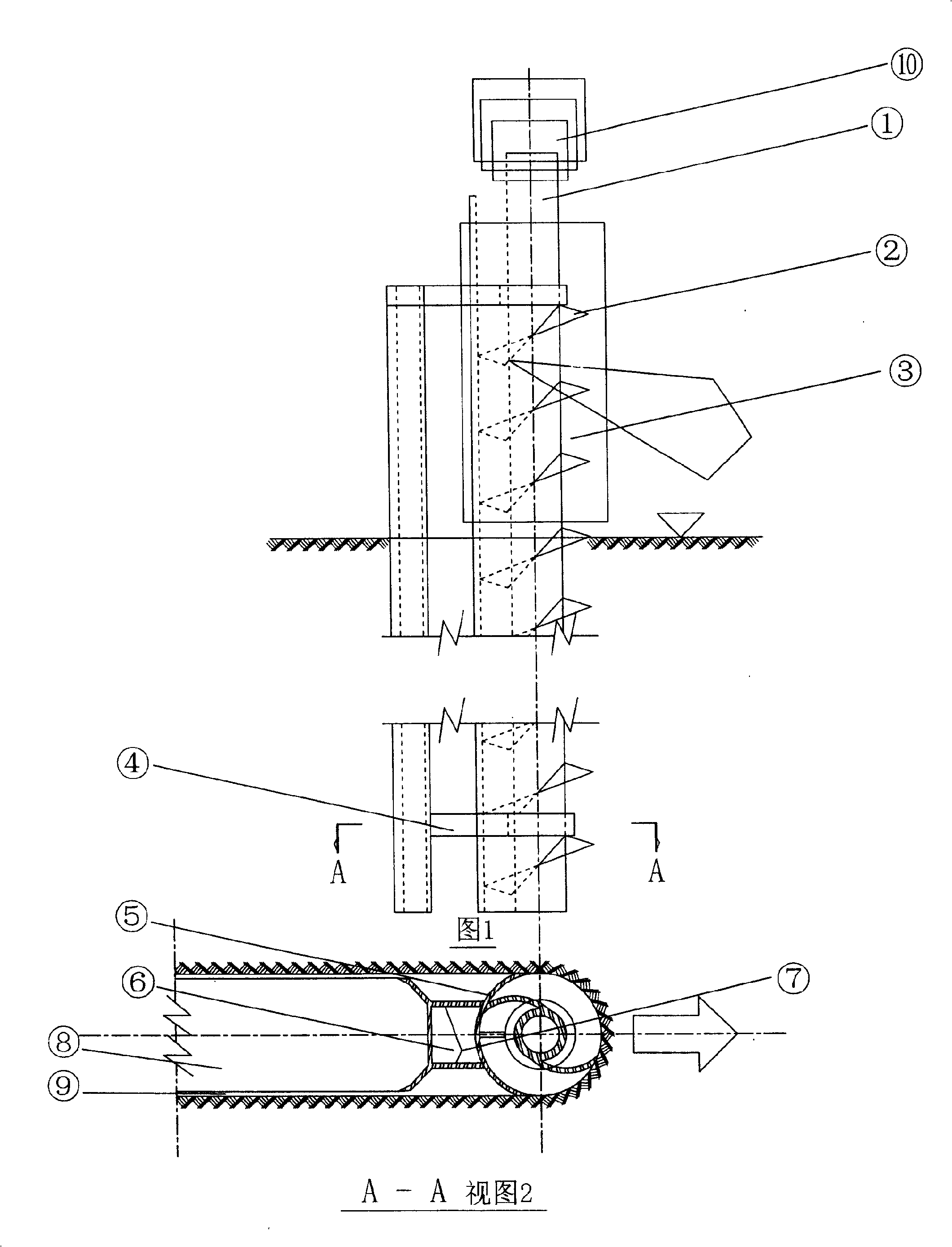
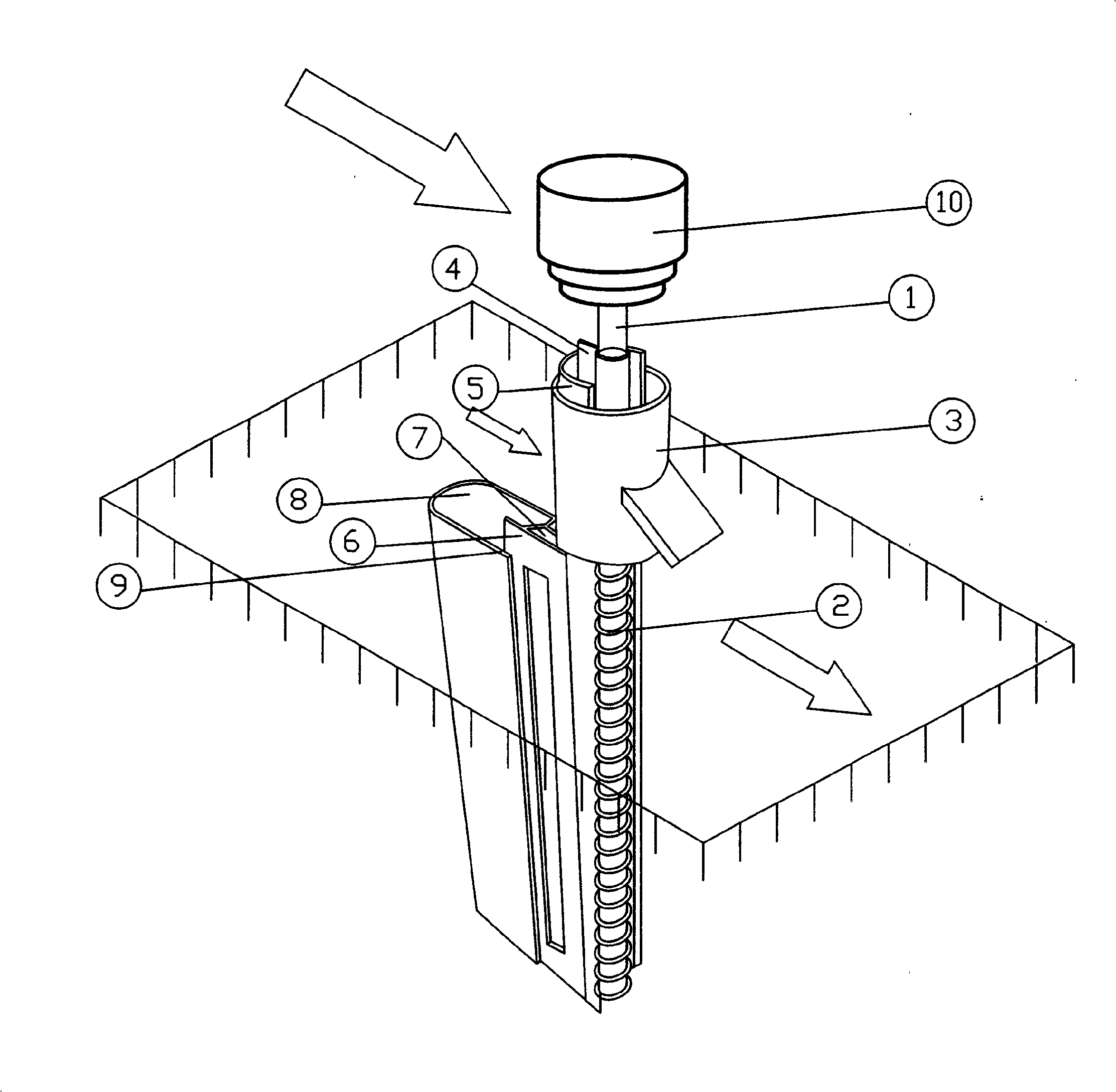
The invention belongs to the civil engineering underground continuous trench construction field, and in particular relates to a method using a rotating drill to produce underground continuous trenches. The method can be performed orderly according to the following steps that: (A) the rotating drill is placed into a soil hole with the designed depth and is driven by external force to make the rotating drill advance on a rotary cut along a continuous trench-forming direction; (B) a meniscus (5) of the outer margin of a drilling blade (2) which is connected with a drill rod (1) by a shaft prevents the soil from flinging backward, which naturally forms a trench (8). The device adopted by the method comprise the following parts that: the middle part of the device is provided with an auger drill which consists of the drill rod (1) and the drilling blade (2), the outer margin of the drilling blade (2) is provided with a blocking and smearing device which consists of the meniscus (5) and an extruding and smearing member (6) and forms a material fixation cabin (7), one end of a supporting part (4) is fixedly connected with an end axle on the meniscus (5) to connect the drill rod (1), a fixed guide sleeve (3) is sleeved outside the meniscus (5) and drives the drill rod (1) of the drilling tool to advance, and the drilling blade (2) rotatablely cuts the soil by a dynamic head (10). The method adapts to the engineering objectives of underground continuous walls, impervious walls, enclosing load bearing walls and pipeline laying, and creates an excellent construction method for reserved construction.
Description
Method and device for making underground continuous trench with rotary drill Technical field The invention belongs to the field of construction of underground continuous trenches in civil engineering works, and particularly relates to a method and device for making underground continuous trenches by a rotary drill in civil engineering works. Background technique Nowadays, in civil engineering, the underground continuous trench is excavated under the condition of mud protection after the guide wall is completed. The equipment is easy to drill, hold the drill, and stuck the drill. At the same time, it is difficult to ensure the accuracy, making the groove wall uneven and uneven. The soil ballast remaining in the trough that is not discharged during the trenching process, the soil particles suspended in the mud gradually settle to the bottom of the trough, and the mud that is scraped off the trough wall when the steel cage is hoisted by brushing the wall and so on is accumulated on...
Claims
Login to View More Application Information
Patent Timeline
 IPC IPC(8): E02D5/18E02F5/04E02D17/06
Inventor王英权王英杰王毅王剑
Owner王英权