Multi-storied garage intelligent carrier
A technology of intelligent handling and three-dimensional garage, which is applied in the field of vehicle carriers, can solve problems such as space cleanliness, temperature and humidity unfavorable for normal operation of equipment, difficult layout of mechanical structures, short trouble-free working time, etc., and achieve novel clamping rods and action methods Unique, solves structural and reliability problems, and increases the application range of vehicles
- Summary
- Abstract
- Description
- Claims
- Application Information
AI Technical Summary
Problems solved by technology
Method used
Image
Examples
Embodiment 1
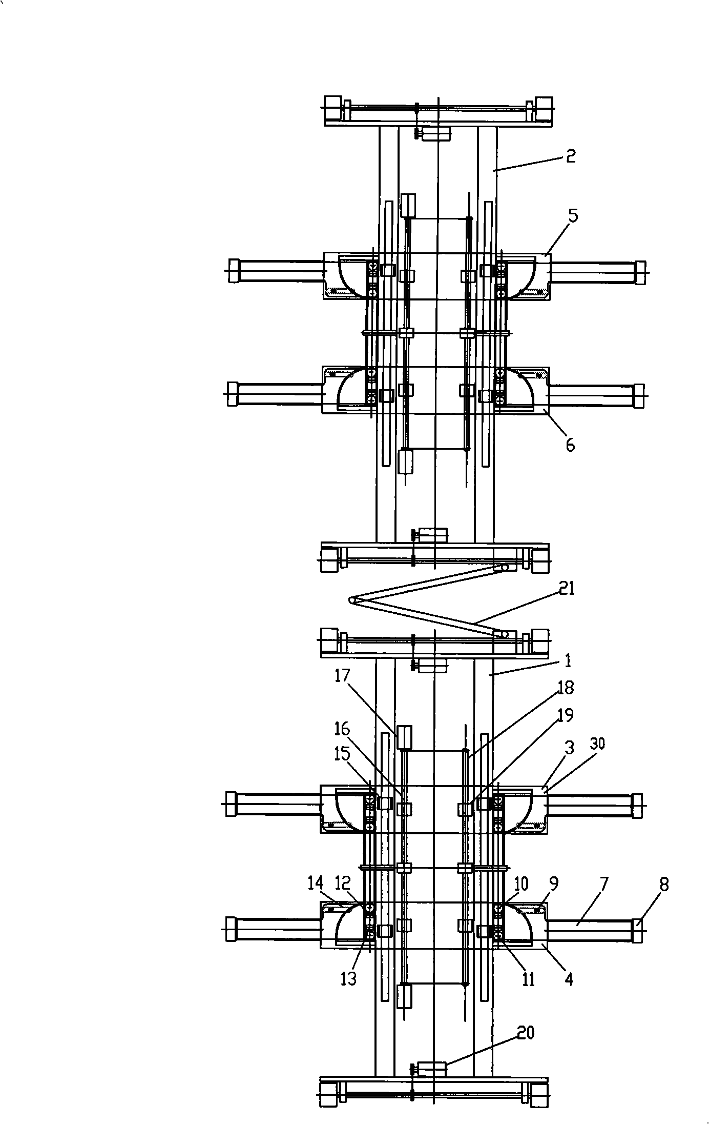
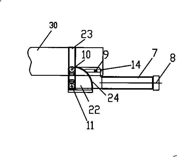
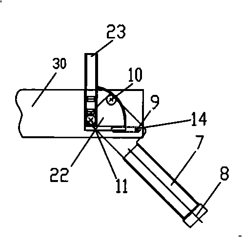
[0032] see figure 1 , as shown in the figure, the present invention discloses a three-dimensional garage intelligent carrier, which includes two car bodies connected by a connecting rod 21, which are the first car body 1 and the second car body 2 respectively. A traveling mechanism and a positioning device are provided on the at least one vehicle body; the structure of the traveling mechanism is a prior art, and will not be described in detail here; the traveling mechanism controls the movement of the carrier through a drive motor 20 . Each vehicle body includes one or more drive motors 20 that drive the overall movement of the carrier. In this embodiment, each vehicle body includes two such drive motors 20 . The positioning device is used to complete the positioning of the vehicle body and the vehicle, which is a prior art and will not be described in detail.
[0033] The two vehicle bodies 1, 2 are respectively provided with at least two push plate mechanisms. In this embo...
Embodiment 2
[0061] The difference between this embodiment and Embodiment 1 is that in this embodiment, the number of push plate mechanisms on each vehicle body has changed from two to one, and through the relative movement of the two vehicle bodies, the two pairs of clamping rods are respectively positioned on the wheels. The inner or outer side of the tire, and then squeeze the tire through the opposite or opposite movement of the two pairs of clamping rods, thereby lifting the vehicle.
[0062] In this embodiment, the carrier includes at least two vehicle bodies connected by a set of connecting rods; a running mechanism and a positioning device are arranged on the at least one vehicle body, and the two vehicle bodies respectively include a push plate mechanism; each of the The push plate mechanism includes the push plate main body, two clamping rods respectively arranged at both ends of the push plate main body, and the transmission mechanism arranged at both ends of the push plate main ...
Embodiment 3
[0064] The difference between this embodiment and Embodiment 1 is that, in this embodiment, the number of vehicle bodies has changed from two to one. The clamp rods move in a straight line opposite to each other to squeeze the front and rear wheels of the car respectively, thereby lifting the car.
[0065] In this embodiment, the carrier includes a vehicle body on which a traveling mechanism and a positioning device are arranged. The vehicle body includes two push pedal mechanisms; The rod, the transmission mechanism arranged at the two ends of the main body of the push plate, the combined guide rail fixed on the vehicle body and having the force support and movement track constraint effect on the clamp rod, and the power device for controlling the movement of the clamp rod; the combined guide rail includes the first A guide unit, a second guide unit, the clamping rod moves linearly along the first guide unit or rotates along the second guide unit under the action of the power...
PUM
 Abstract
Description
Claims
Application Information
 - R&D
- Intellectual Property
- Life Sciences
- Materials
- Tech Scout
- Unparalleled Data Quality
- Higher Quality Content
- 60% Fewer Hallucinations
Browse by: Latest US Patents, China's latest patents, Technical Efficacy Thesaurus, Application Domain, Technology Topic, Popular Technical Reports.
© 2025 PatSnap. All rights reserved.Legal|Privacy policy|Modern Slavery Act Transparency Statement|Sitemap|About US| Contact US: help@patsnap.com


