Solar energy heat sink

A solar thermal storage and thermal storage technology, applied in the field of solar thermal storage, can solve the problem of no efficient, long-term, low-cost solar storage method, etc., and achieve the effects of saving time and effort in management, protecting the environment, and effectively storing

Inactive Publication Date: 2008-10-22
STATE GRID CORP OF CHINA +1
View PDF0 Cites 8 Cited by
  • Summary
  • Abstract
  • Description
  • Claims
  • Application Information

AI Technical Summary

Problems solved by technology

[0004] In order to solve the problem that there is no efficient, long-term and low-cost solar energy storage method in the prior art, the present invention provides a solar thermal storage

Method used


Image

  • Solar energy heat sink
  • Solar energy heat sink
  • Solar energy heat sink

Examples


Embodiment 1

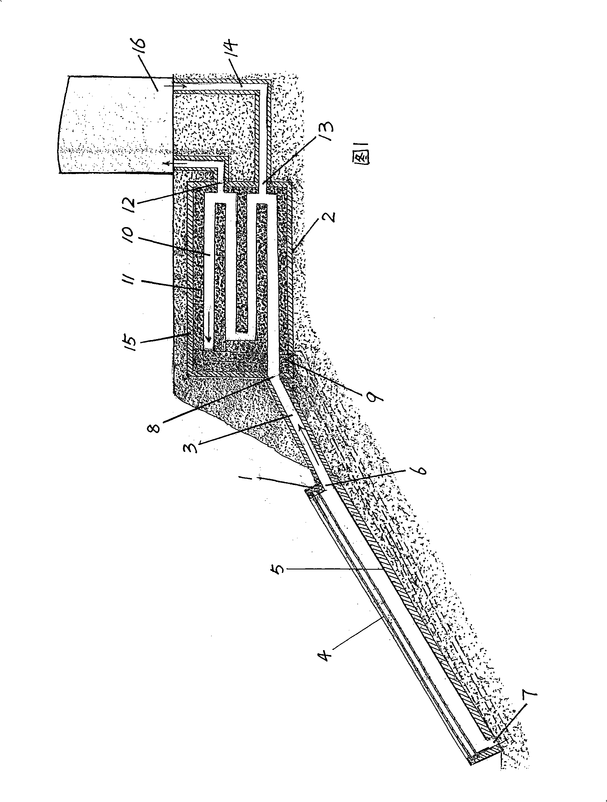
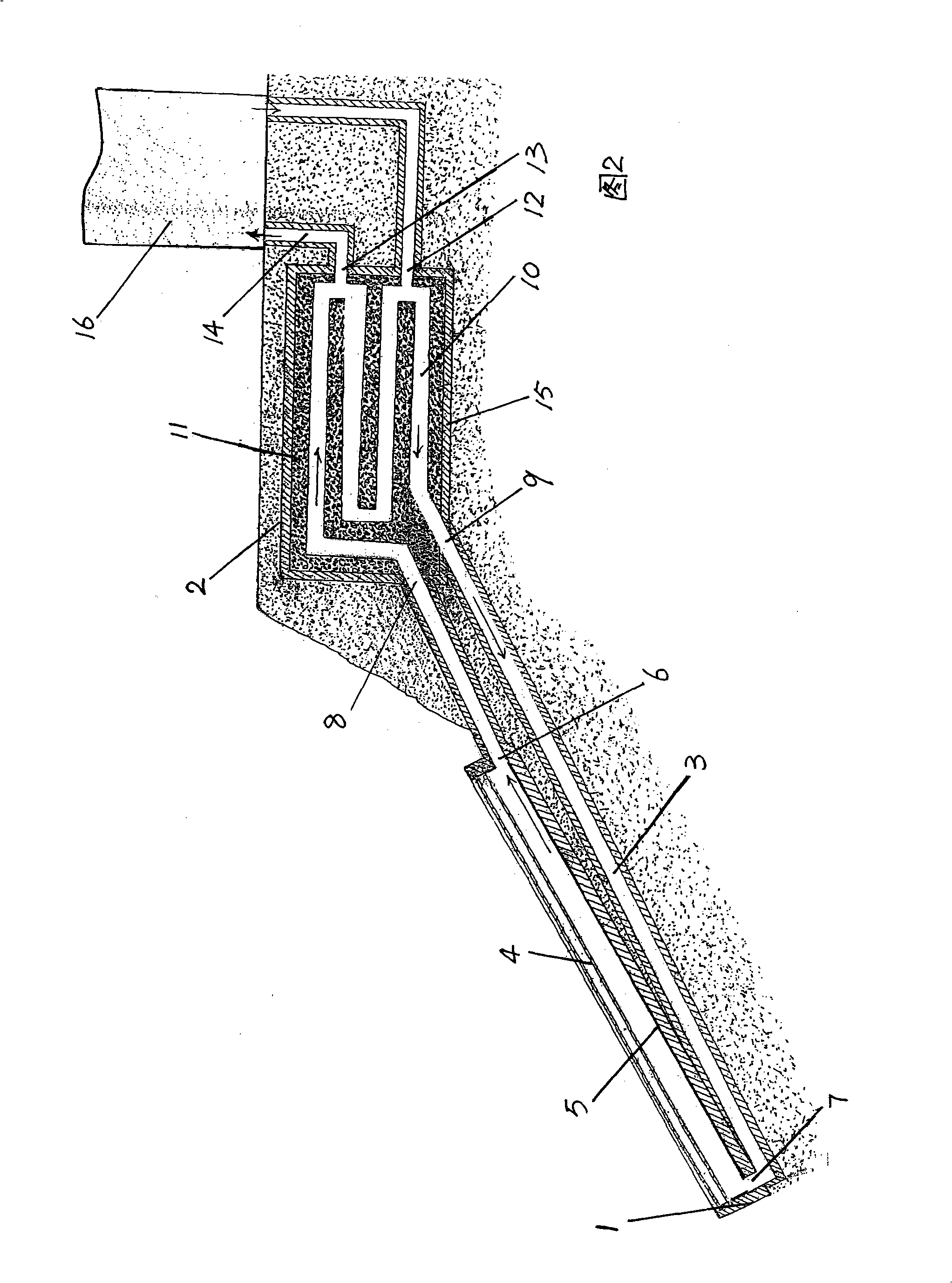
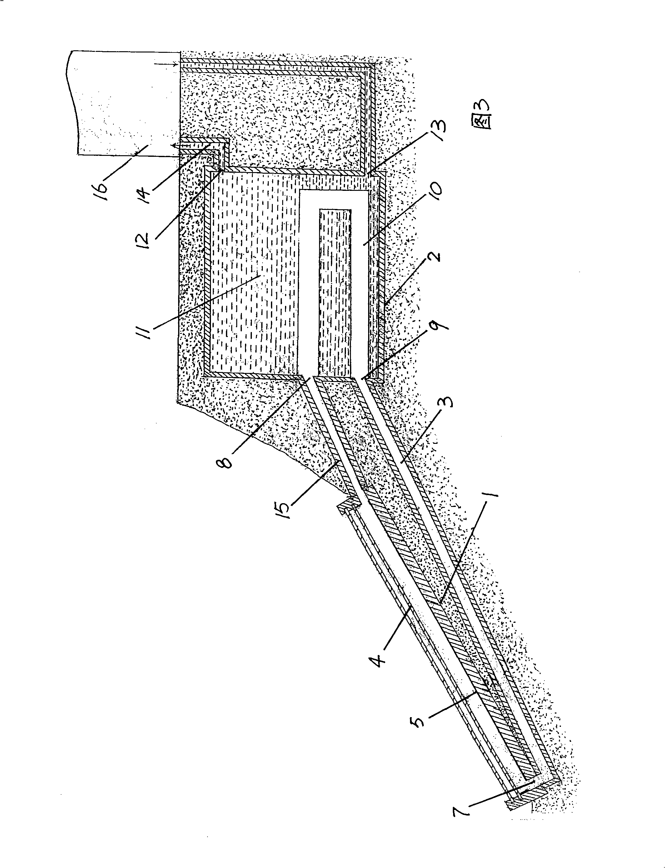
[0051] Embodiment 1: as shown in Figures 1, 2, and 3, on the ground is a thermal building 16, in the soil 1 meter below the ground is a heat store 2, and on the slope further down is a heat collection box 1, a heat collection box 1 The air outlet 6 of the box is connected with the storage air inlet 8 of the thermal storage 2 through the circulating air channel 3 . The heat storage air passage 10 is in the heat storage material 11 in the heat storage 2 , one end of the heat storage air passage 10 is connected to the storage air inlet 8 , and the other end is connected to the storage air outlet 9 . The storage air outlet 9 of the heat storage 2 is connected with the box air inlet 7 of the heat collection box 1 through the circulating air channel 3 .

[0052] After sunlight heats the air in the heat collection box 1, the hot air flows from the box air outlet 6 above the box body through the circulation air passage 3 and the storage air inlet 8 into the heat storage air passage 10...

Embodiment 2

[0055] Embodiment 2: as Figure 4~5 As shown, the heat collection box 1 is on the ground, and the heat storehouse 2 is under the ground. In order to allow the hot air to flow downward and the cold air to flow upward, a heat pump box 17 is added. The specific structure of the heat pump box 17 is that the box air outlet 6 above the heat collecting box 1 is connected to the storage air inlet 8 below the heat storage 2 through a circulating air duct, and the storage air outlet 9 above the thermal storage 2 is connected through a circulating air duct. On the pump air inlet 19 below the pump heat box 17, the pump air outlet 18 above the heat pump heat box 17 is connected to the box air inlet 7 below the heat collection box 1 through the circulation air passage, which constitutes a three-in-one series cycle flow system.

[0056] When the heat pump box 17 was irradiated by the sun, when the hot gas flowed upwards, it sucked the gas flow in the heat store 2, and when the gas flow in t...

Embodiment 3

[0057] Embodiment 3: as Figure 6-7 As shown, there are mainly heat collecting box 1, heat building 16, heat storage 2, heat pump box 17, circulating air duct 3, blower 22, coal-fired boiler 23, air resistance 24, special air pump 25 and other components.

[0058] The box air outlet 6 of the heat collecting box 1 is connected with the storage air inlet 8 of the thermal storage 2 through the circulation air passage, and the storage air outlet 9 of the thermal storage 2 is connected with the pump air inlet 19 of the heat pump box 17 through the circulation air passage 3 Next, the pump air outlet 18 of the heat pump box 17 is connected with the box air inlet 7 of the heat collection box 1 through a circulating air passage. Blower 22 is located at the box air outlet 6 of heat collection box 1, air resistance 24 is arranged on the circulating air passage outside the storehouse air outlet 9 of heat storehouse 2 as shown in Figure 16, and fan type air pump 25 is located at the storeh...


PUM


Abstract

The invention belongs to the solar heat storage technical field, in particular to a solar heat reservoir, which solves the problem that a solar energy storage method with high efficiency, long service lite and low cost does not exist in the prior art. The solar heat reservoir comprises a heat collecting device and a heat storage device. The heat storage device is connected with a heat consuming device. The heat collecting device comprises a heat collecting box, an upper part of the heat collecting box is provided with light transmission glass, and the bottom of the heat collecting box is provided with an absorbing coating. The heat storage device comprises the heat reservoir the inside of which is provided with a heat storage air passage, the outside of the heat storage air passage is of heat storage material, the periphery of the heat reservoir is provided with heat insulating material, and the heat collecting box is connected with the heat reservoir and the heat reservoir is arranged under the ground. The solar heat reservoir has the advantages of realizing effective storage of the solar energy, using the solar energy at any time, time and labor conservation for management, low cost, safety, clean and sanitation, and has a far-reaching meaning to environmental protection.

Description

technical field [0001] The invention belongs to the technical field of solar heat storage, and in particular relates to a solar thermal store. Background technique [0002] At present, there are many technologies in the development and utilization of solar energy, including umbrella-type solar cookers, box-type solar cookers, photoelectric effect cells, etc., some of which have formed scale, and some have yet to be perfected. Only there is no high-efficiency, long-term, and low-cost solar energy storage technology to realize the function of solar heating, so that solar heating can be used for heating, plastic greenhouses, and thermal power generation. This aspect is still blank in the prior art. [0003] In recent years, environmental pollution has become an increasingly serious problem that plagues human society. Solar energy is clean, hygienic, inexhaustible and inexhaustible. It does not need to be mined or transported, and it can be collected in sunny places. As long ...

Claims


Application Information

Patent Timeline
Patent Type & Authority Applications(China)
IPC IPC(8): F24J2/00F24J2/04F24J2/34F24J2/46F28D20/00F24S10/40
CPCY02E60/142Y02E10/44Y02E70/30Y02E60/14
Inventor 乔君旺
Owner STATE GRID CORP OF CHINA
Why Eureka
Try Eureka