
Method for enhancing optical fibre gyroscope output accuracy

A fiber optic gyroscope, high-precision technology, applied in Sagnac effect gyroscopes, measuring devices, instruments, etc., can solve the problem of reducing the accuracy of feedback and bias voltages, inaccurate feedback and bias voltages, and reducing the output accuracy of fiber optic gyroscopes and other problems, to achieve the effect of improving static accuracy, easy operation, and simple and convenient compensation method

Inactive Publication Date: 2008-10-22
ZHEJIANG UNIV
View PDF0 Cites 7 Cited by
  • Summary
  • Abstract
  • Description
  • Claims
  • Application Information

AI Technical Summary

Problems solved by technology

[0004] In the signal processing circuit-digital-to-analog converter-post-amplification drive circuit loop, the integral non-linear error of the digital-to-analog converter is the most important source of error, the existence of this error reduces the accuracy of the feedback and bias voltage, resulting in Inaccurate feedback and bias voltage, which reduces the output accuracy of the fiber optic gyroscope

Method used


Image

  • Method for enhancing optical fibre gyroscope output accuracy
  • Method for enhancing optical fibre gyroscope output accuracy
  • Method for enhancing optical fibre gyroscope output accuracy

Examples


Embodiment Construction

[0033] Below in conjunction with accompanying drawing and implementation the present invention will be further described:

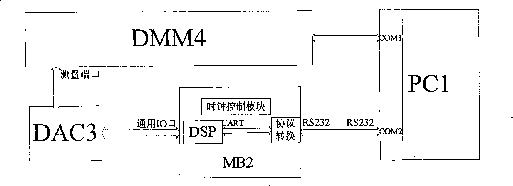
[0034] figure 1 It is a schematic block diagram of the digital code input-analog value output test system of the digital-to-analog converter. The system consists of a computer (PC1), a motherboard (MB2), a digital-to-analog converter (DAC3) and a high-precision multimeter (DMM4). PC1 is connected to MB2 through the RS232 port. The main device of MB2 is DSP, and its UART port is output by RS232 protocol through the protocol conversion chip, which is used to communicate with PC1; its general IO port is connected to DAC3, and is used to send digital codes to DAC3; the internal clock control module coordinates the timing. DAC3 is connected with DMM4, and DMM4 is connected with another RS232 port of PC1. DMM4 is used to measure the analog output value of DAC3 and send the result back to PC1.

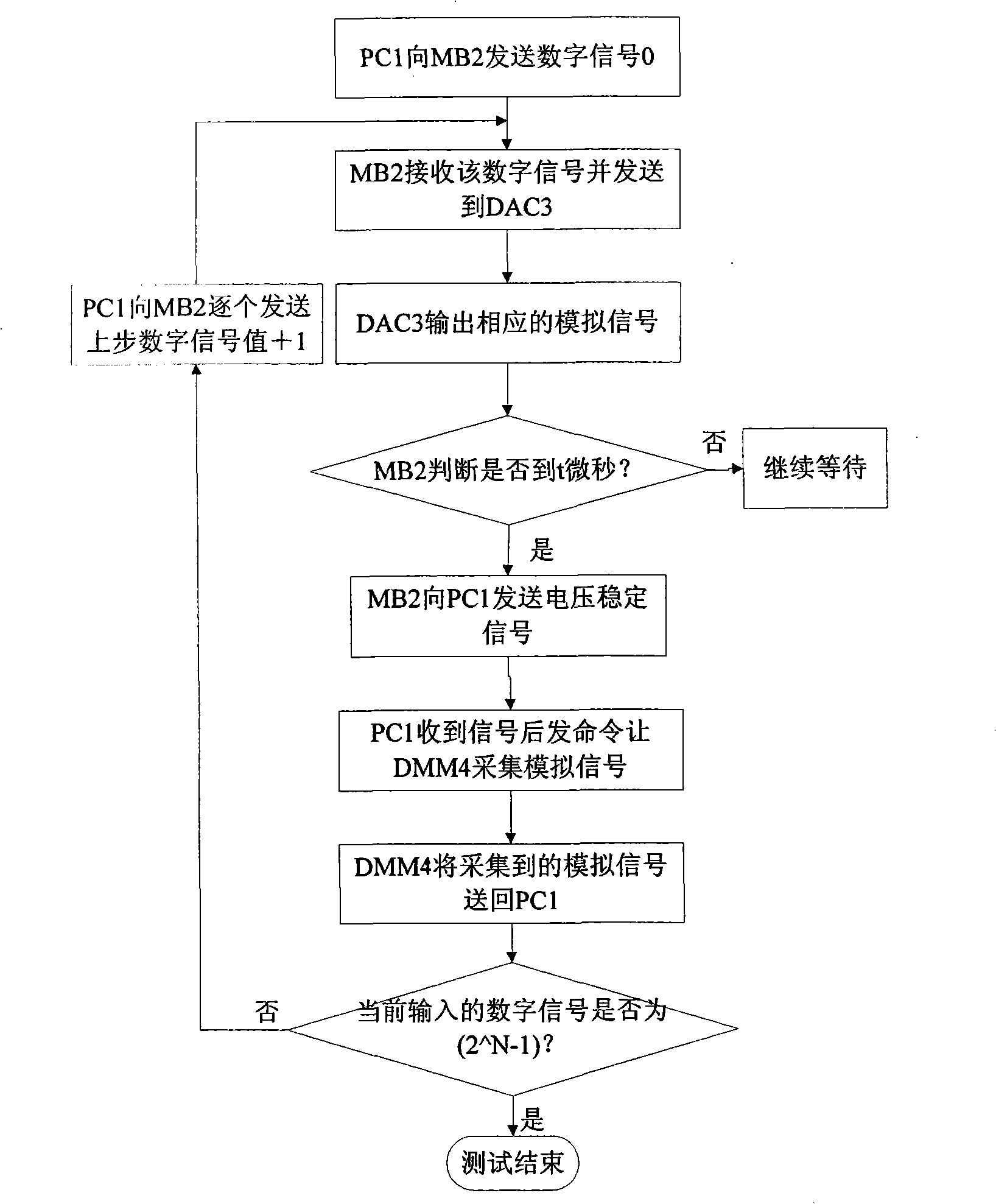
[0035] figure 2 It is a test flow chart of digital code input-a...


PUM


Abstract

The invention discloses a method for increasing the fiber optic gyro scope output precision. The method comprises the steps of: constructing a testing system which inputs digital codes and outputs simulated values of the analog-digital converter; obtaining a comparison table which is output through inputting responded simulated values of different digital codes from 0 to 2N-1 of the analog-digital converter; calculating to obtain an integration non-linear error comparison table corresponding to different digital code input of the analog-digital converter; compensating integration non-linear errors of the analog-digital converter through a hardware compensating method of adding a subtracter; and obtaining accurate analog-digital converter output. The method effectively lowers false output which is caused by the integration non-linear errors of the analog-digital converter, guarantees the accuracy of fiber optic gyro scope feedback and offset voltage, can regulate compensated integration non-linear error parts according to parameter differences of the analog-digital converter, and effectively improves the output precision of the fiber optic gyro scope.

Description

technical field [0001] The invention relates to the field of optical fiber sensors in optoelectronic technology, in particular to a method for improving the output precision of an optical fiber gyroscope. More specifically, it refers to a method of improving the output accuracy of the fiber optic gyroscope by compensating the integral nonlinear error of the digital-to-analog converter by hardware. Background technique [0002] The modulation of the closed-loop FOG has two main functions: dynamic bias and closed-loop feedback. Among them, the dynamic bias makes the system work at the most sensitive ±π / 2 operating point, and the closed-loop feedback provides an additional phase to compensate for the Sagnac phase shift caused by the system rotation, keeping the fiber optic gyroscope working accurately at ±π / 2 operating point, so as to obtain a scale factor with good linearity. [0003] Current implementations of dynamic biasing and closed-loop feedback are accomplished by app...

Claims


Application Information

Patent Timeline
Patent Type & Authority Applications(China)
IPC IPC(8): G01C19/72G01C25/00
Inventor 程淼胡慧珠舒晓武刘承
Owner ZHEJIANG UNIV
Learn More