
Multi- frequency range multifunctional electronic label

An electronic tag, multi-band technology, applied in the field of radio frequency identification, can solve the problems of reducing the power used, the identification rate is not high enough, and the microwave antenna cannot be accommodated, and achieves the effect of preventing illegal disassembly, saving investment, and improving the success rate and efficiency.

Inactive Publication Date: 2008-10-22
ZHEJIANG JIUZHOU ELECTROMECHANICAL ENG
View PDF2 Cites 11 Cited by
  • Summary
  • Abstract
  • Description
  • Claims
  • Application Information

AI Technical Summary

Problems solved by technology

[0006] 1. For the comprehensive replacement of the IC card, it will inevitably cause a serious waste of resources
Due to the implementation of the ambiguous path identification system, the 13.56M microwave antenna and contact interface in the IC card currently used can no longer meet the needs, and a 433M / 915M / 2.4G microwave antenna needs to be added in the IC card
On the one hand, the external dimensions of existing IC cards cannot accommodate the existing 433M / 915M / 2.4G microwave antennas; Production
Therefore, once the ambiguous path identification system is implemented, it is necessary to completely replace the existing IC card, which will not only cause a serious waste of resources, but also cause a waste of funds
[0007] 2. The cost of IC card is high, and the identification rate is not high enough
Due to the limitation of the size of the IC card, its battery capacity is relatively small. In order to meet the requirements of the same usage time, it is bound to require the IC card to reduce the power used when it is awakened by the roadside antenna.
On the one hand, reducing the power usage will greatly increase the cost. On the other hand, due to the reduction in power usage, the antenna's performance will inevitably affect its identification rate.

Method used


Image

  • Multi- frequency range multifunctional electronic label
  • Multi- frequency range multifunctional electronic label

Examples


Embodiment

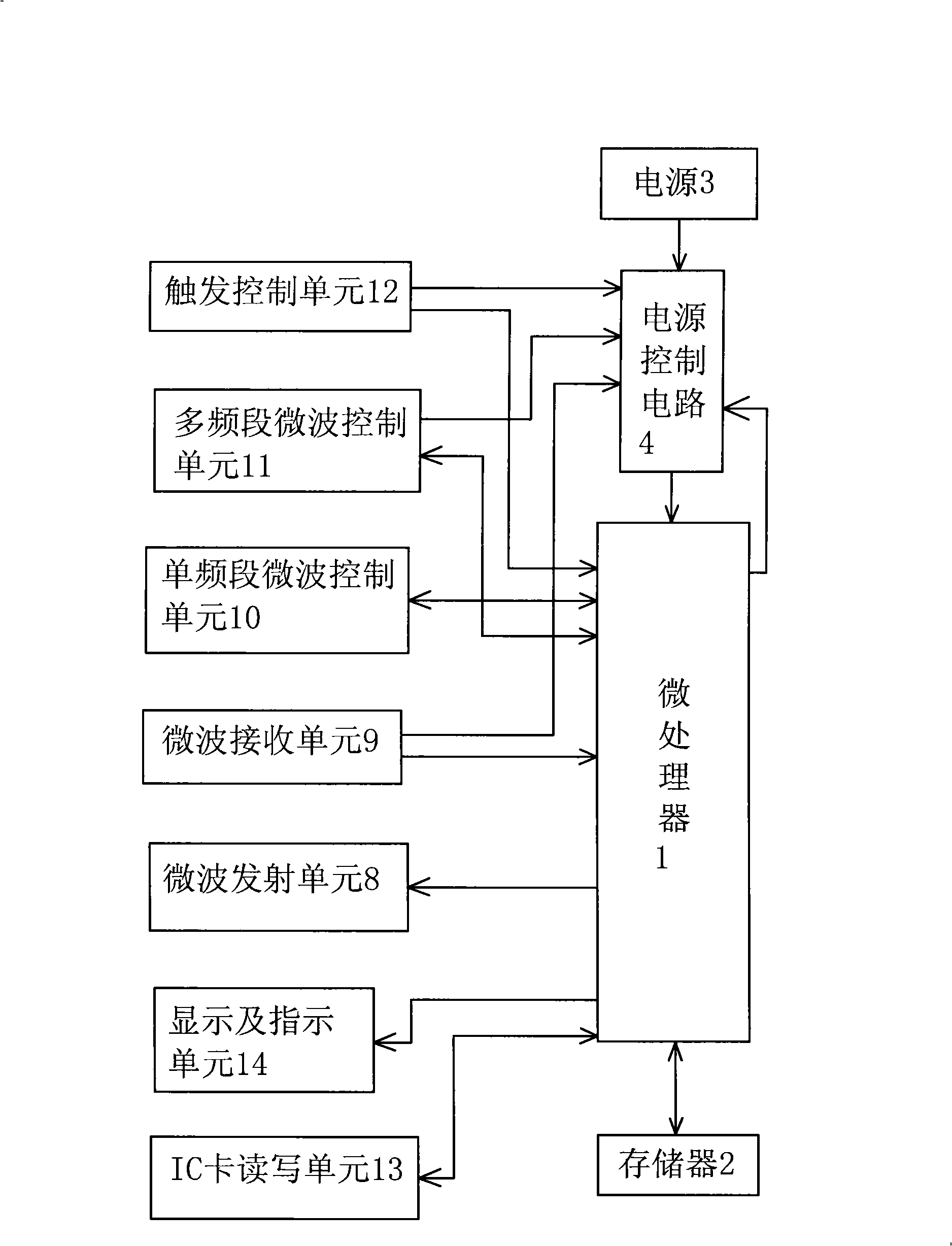
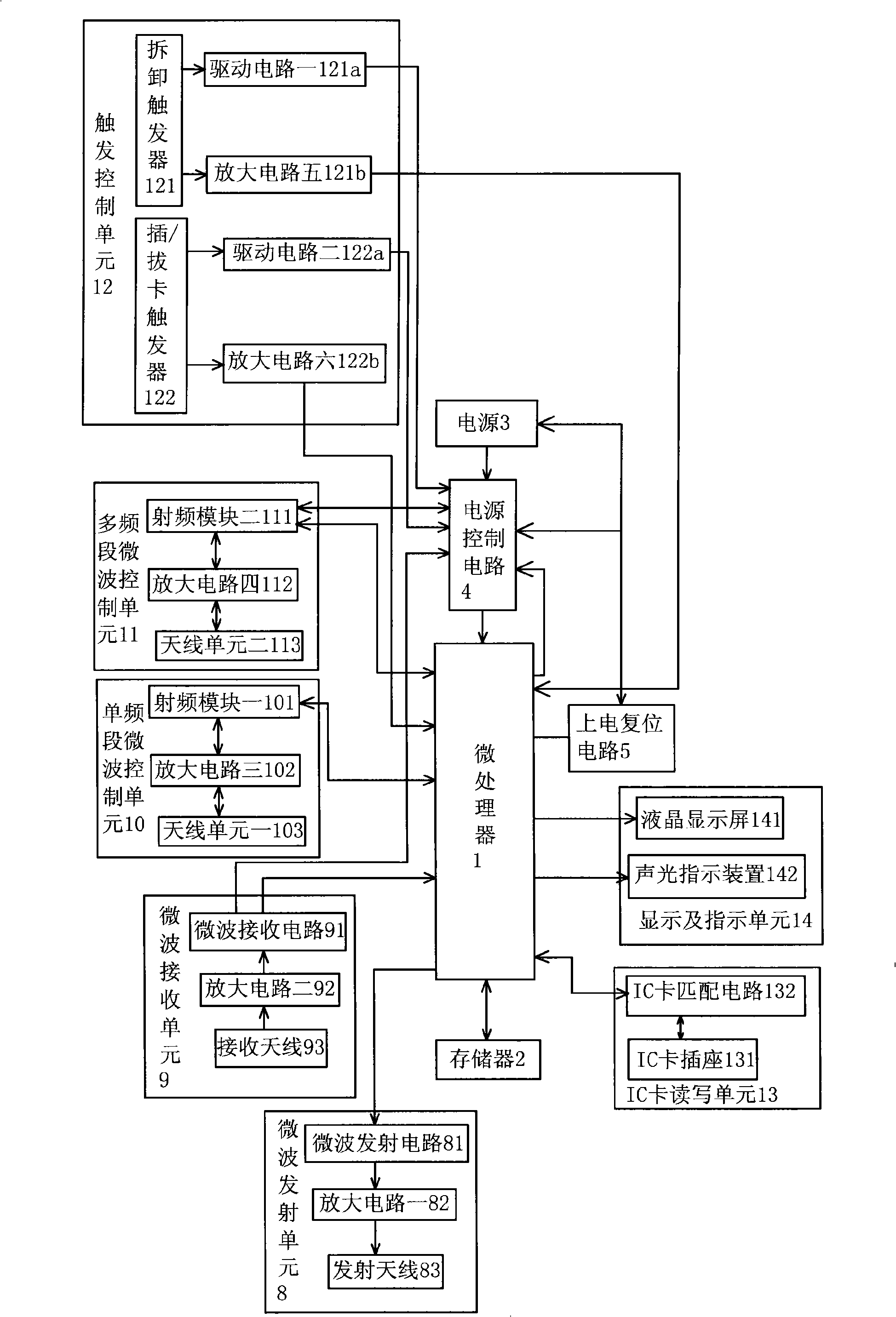
[0029] Such as figure 1 with figure 2 As shown, the novel multi-band multifunctional electronic tag includes a microprocessor 1, a memory 2 connected to the I / O terminal of the microprocessor 1, a power supply 3 connected to the microprocessor 1 through a power control circuit 4, and the microprocessor The I / O terminal of 1 is also connected to a power-on reset circuit 5, which is connected to the power supply 3 and the power control circuit 4 respectively. The I / O end of the microprocessor 1 is also connected with a microwave transmitting unit 8, a microwave receiving unit 9, a single-band microwave control unit 10, a multi-band microwave control unit 11, a trigger control unit 12, and an IC card for information interaction. And the information in the IC card is read into the IC card read-write unit 13 in the memory 2;

[0030] The microwave transmitting unit 8 is a 5.8G microwave transmitting unit, which includes a microwave transmitting circuit 81 , an amplifying circuit...


PUM


Abstract

The invention relates to a novel electric label with multiple frequency range and multiple functions. The electric label comprises a micro processor, a memory connected with an I / O end of the micro processor, a power supply connected with the micro processor by a power supply control circuit and a powerup reset circuit connected with the I / O end of the micro processor, wherein the powerup reset circuit is also connected with the power supply and the power supply control circuit respectively; the invention is characterized in that the I / O end of the micro processor is also connected with a microwave emitting unit, a microwave receiving unit, a single frequency range microwave control unit, a multiple frequency range microwave control unit, a triggering control unit and an IC card read-write unit which is used to exchange information with the IC card and read information stored in the IC card in the memory; the multiple frequency range microwave control unit, the triggering control unit and the microwave receiving unit are all connected with the power supply control circuit. The solidification of the I / O end of the micro processor conforms to the operation and logic program of the short-range wireless communication protocol specification. The electric label has the advantages of low cost, high working efficiency and small volume.

Description

technical field [0001] The invention relates to the technical field of radio frequency identification, in particular to a novel multi-band multifunctional electronic label based on a special short-range communication protocol and suitable for expressway electronic non-stop toll collection and ambiguous path identification. Background technique [0002] Electronic non-stop toll (ETC) technology and ambiguous path recognition technology are key development projects in the field of intelligent transportation at present, and are important means to realize road intelligence and informatization. Among them, the electronic non-stop toll collection technology can ensure reliable payment while ensuring that vehicles pass through the toll booth quickly, so as to effectively improve the traffic bottleneck situation of the current urban entrance and exit toll booths. The ambiguous path recognition technology can provide perfect and clear driving data of vehicles, and provide a basis for...

Claims


Application Information

Patent Timeline
Patent Type & Authority Applications(China)
IPC IPC(8): G06K19/07G06K7/00G07B15/00G07B15/06
Inventor 王长华李晓春章海燕陶杰秦勇
Owner ZHEJIANG JIUZHOU ELECTROMECHANICAL ENG
Learn More