
Eureka
For R&D, Eureka makes reading and utilizing patents & technical documents easy.
Eureka AIR
Designed for self-driven R&D workflows. Generate viable solutions, solve complex R&D challenges, empower your innovation with AI.

Eureka Materials
Designed for material experts only. Revolutionize your material R&D, from search, analyze, to developing new materials.

TechResearch
Generate reliable direction feasibility study reports for your R&D in just a few steps.

TechSeek
Discover and master advanced knowledge NOW. Basics, ideas, possibilities, all at once.

TechMind
As an expert in R&D Theories, TechMind can generates customized viable solutions instantly.

TechRisk
Analyze your overall solution with one click, know your potential R&D risks in advance.

TechMonitor
Get weekly tech updates, stay abreast of the latest tech innovations and key insights.
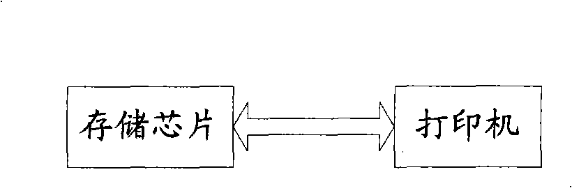
Method and circuit for simulation of response characteristic applied to ink jet printer
An inkjet printer and stimulus-response technology, applied in printing, electrical components, impedance networks, etc., can solve problems such as environmental pollution, inconvenience, and cost increases, and achieve the effects of reducing costs, facilitating costs, and reducing environmental pollution
- Summary
- Abstract
- Description
- Claims
- Application Information
AI Technical Summary
Problems solved by technology
Method used
Image

Examples
Embodiment 1
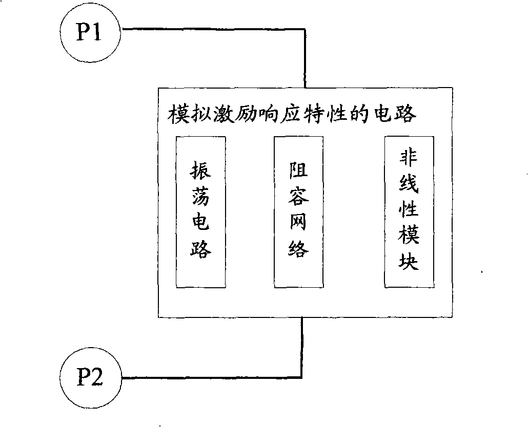
[0069] Figure 5 It is a structural schematic diagram of Embodiment 1 of a circuit for simulating excitation-response characteristics provided by the present invention. The analog circuit is composed of an oscillating circuit, a resistance-capacitance network, a nonlinear module, and a positive and negative polarity circuit.
[0070] Among them, the two ends of the positive and negative polarity circuits are respectively connected to the resistance-capacitance network; the nonlinear module and the oscillating circuit are embedded in the resistance-capacitance network. The inkjet printer adds an excitation signal between P3 and P4 to detect the excitation response characteristics of the circuit.
[0071] In this embodiment, the non-linear module, the oscillating circuit and the positive and negative polarities are all embedded in the resistance-capacitance network for illustration.
[0072] Among them, the oscillating circuit can be any circuit capable of generating oscillatin...
Embodiment 2
[0085] Figure 7 It is a structural schematic diagram of the second embodiment of the circuit for simulating the excitation response characteristics provided by the present invention. The analog circuit is composed of an oscillating circuit, a resistance-capacitance network, a nonlinear module, and a positive and negative polarity circuit. The positive and negative polarity circuit has three ports, two ends of which are respectively connected to the resistance-capacitance network, and the third end is grounded; the nonlinear module and the oscillation circuit are embedded in the resistance-capacity network, and the two terminals P7 and P8 in the figure are printers The stimulated end is used for the inkjet printer to add an excitation signal between P7 and P8 to detect the excitation response characteristics of the circuit.
[0086] In this embodiment, the non-linear module, the oscillation circuit and the positive and negative polarity circuits are all embedded in the resista...
Embodiment 3
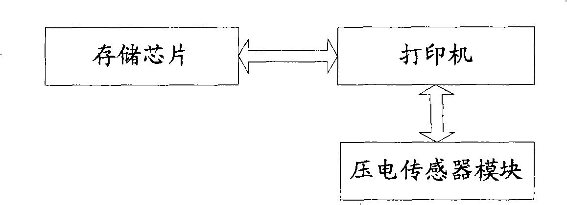
[0099]In the present invention, the circuit for simulating the stimulus response characteristic can also be connected with the storage chip bound on the ink cartridge, specifically, the control unit of the storage chip can be connected with the oscillation circuit. When the memory chip detects that the ink remaining in the ink cartridge is empty in the stored printing information, it sends a control signal to the oscillation circuit of the circuit through the control unit. After the oscillation circuit receives the control signal, it changes the oscillation circuit to receive The characteristics of the excitation response obtained after receiving the excitation signal, that is, the resonance characteristic of the excitation response indicating that the ink in the ink cartridge is empty, makes the inkjet printer know that the ink in the ink cartridge is empty, and informs the user to replace the ink cartridge or / and stop printing.
[0100] In this example, the circuit used is ...
PUM
 Abstract
Description
Claims
Application Information
 - R&D Engineer
- R&D Manager
- IP Professional
- Industry Leading Data Capabilities
- Powerful AI technology
- Patent DNA Extraction
Browse by: Latest US Patents, China's latest patents, Technical Efficacy Thesaurus, Application Domain, Technology Topic, Popular Technical Reports.
© 2024 PatSnap. All rights reserved.Legal|Privacy policy|Modern Slavery Act Transparency Statement|Sitemap|About US| Contact US: help@patsnap.com