
Semiconductor packaging structure

A packaging structure and semiconductor technology, used in semiconductor devices, semiconductor/solid-state device components, electrical solid-state devices, etc., can solve the problems of through-silicon via technology potential not being fully utilized, and reduce stress, reduce The effect of connecting spacing, increasing feasibility

Active Publication Date: 2008-10-29
ADVANCED MFG INNOVATIONS INC
View PDF0 Cites 11 Cited by
  • Summary
  • Abstract
  • Description
  • Claims
  • Application Information

AI Technical Summary

Problems solved by technology

Therefore, the potential of TSV technology has not been fully utilized

Method used


Image

  • Semiconductor packaging structure
  • Semiconductor packaging structure
  • Semiconductor packaging structure

Examples


Embodiment Construction

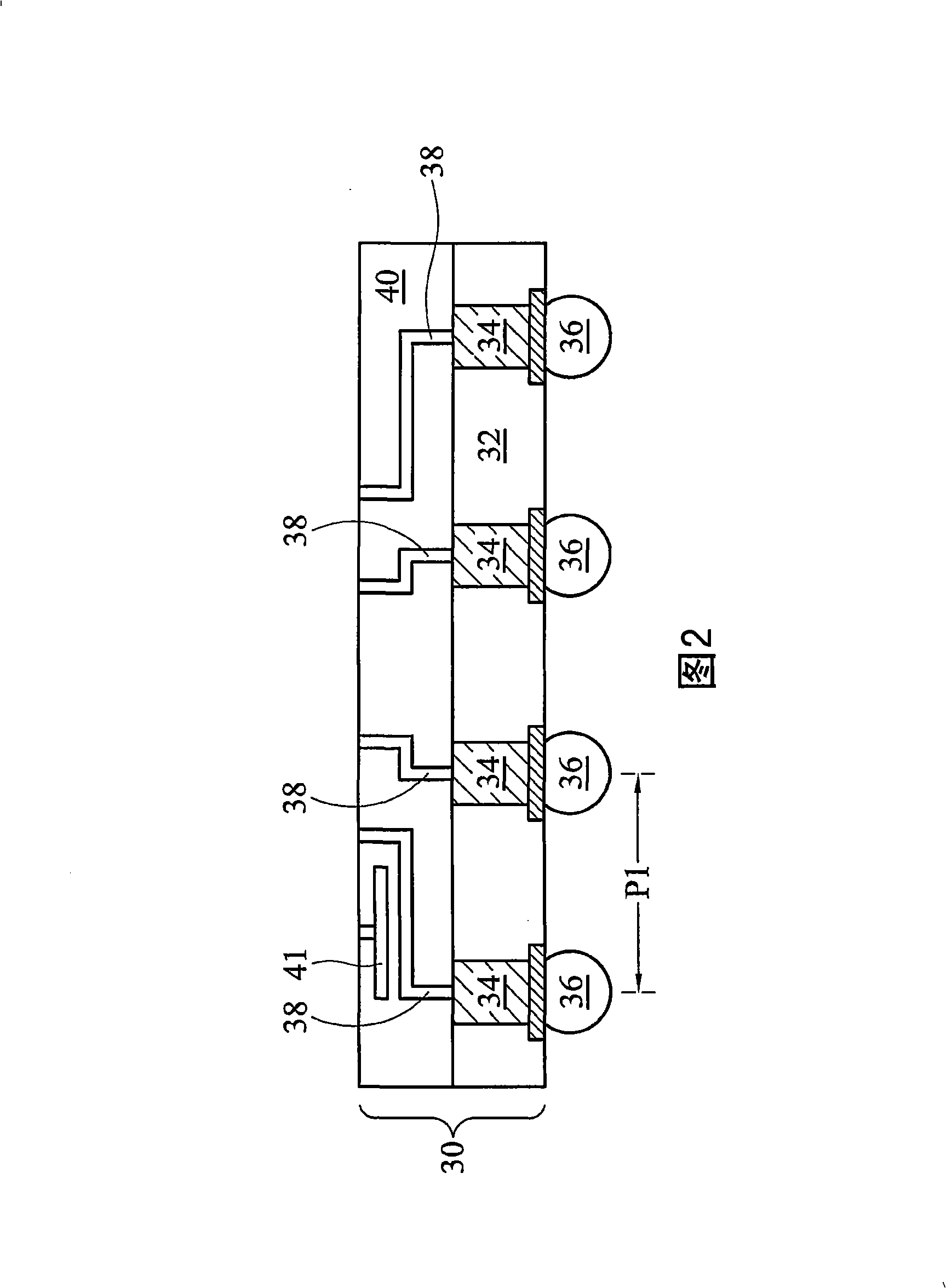
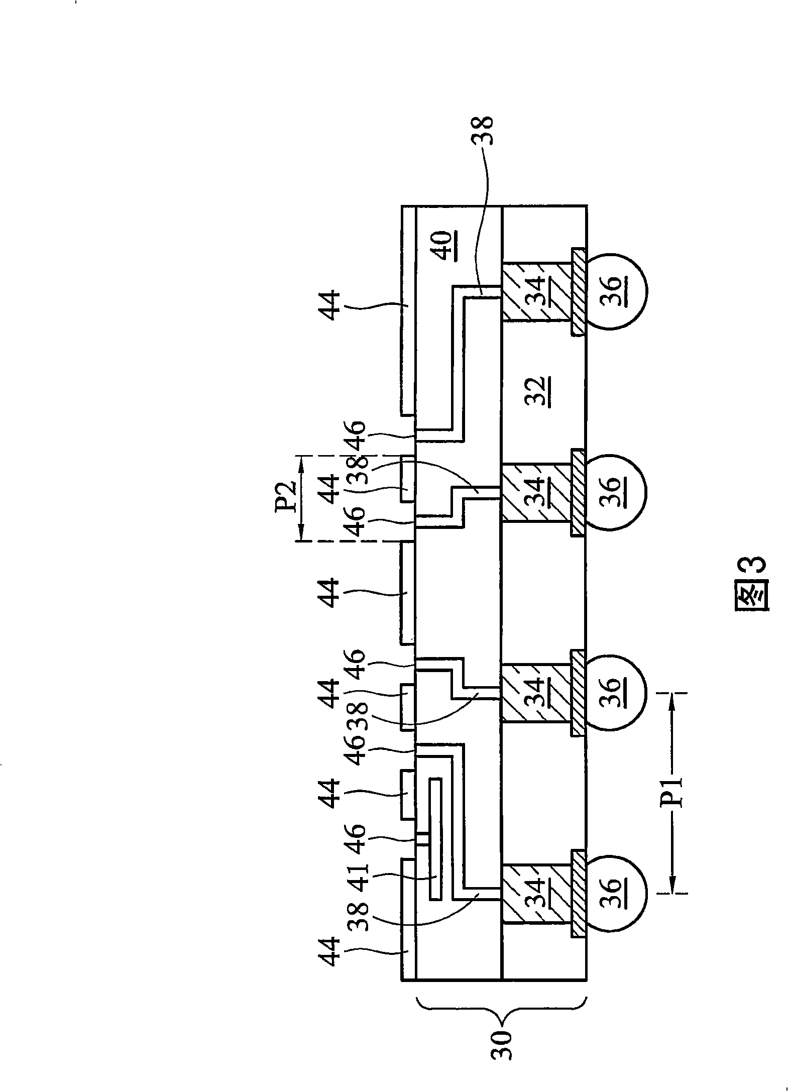
[0057] FIG. 2 shows interposer 30 . In a preferred embodiment, interposer 30 is a silicon-containing interposer including a silicon-containing substrate 32 . Preferably, the thickness of silicon-containing substrate 32 is less than about 750 μm, and more preferably less than 150 μm. In one embodiment, the substrate 32 includes commonly used materials, such as inorganic materials, organic materials, ceramics or multi-layer materials of the above materials. A semiconductor chip (also referred to as a die in the art) intended to be connected to the interposer 30 is usually formed on a silicon substrate. The coefficient of thermal expansion (CTE) of the silicon-containing interposer 30 is not much different from that of the semiconductor chip, so the stress caused by the mismatch of the coefficient of thermal expansion (CTE) can be significantly reduced. Furthermore, the existing silicon process technology can be used to form a silicon-containing interposer, which not only has h...


PUM


Abstract

A semiconductor package structure and the methods for forming the same are provided. The semiconductor package structure includes an interposer; a first plurality of bonding pads on a side of the interposer; a semiconductor chip; and a second plurality of bonding pads on a side of the semiconductor chip. The first and the second plurality of bonding pads are bonded through metal-to-metal bonds.

Description

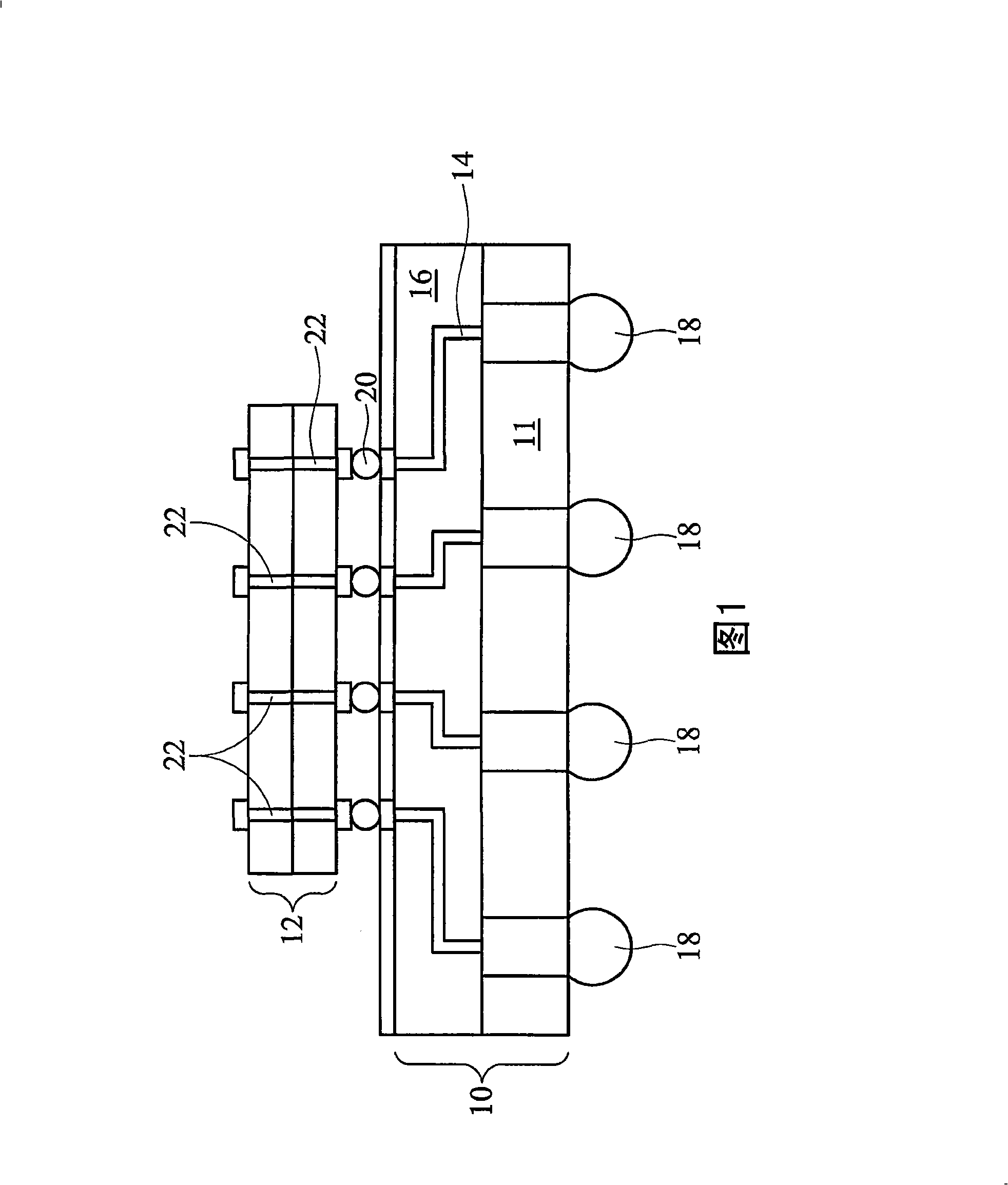
technical field [0001] The present invention relates to an integrated circuit process, and in particular to an electronic packaging process, especially the connection of bare chips on an interposer. Background technique [0002] In the packaging of integrated circuits, interposers can be used as connection paths for space conversion between semiconductor die and packaged parts. For example, tight bonding pads on a semiconductor die can cause packaging difficulties, so interposers can be used to increase the pitch of the semiconductor die. In this example, the first side of the interposer has a first pitch that corresponds to the pitch of the semiconductor dies attached thereto. The bonding pads on the second side have a second pitch for connecting to the package substrate, wherein the second pitch is greater than the first pitch. [0003] FIG. 1 shows a conventional package structure including an interposer 10 and a die 12 connected to the interposer. Typically an interpo...

Claims


Application Information

Patent Timeline
Patent Type & Authority Applications(China)
IPC IPC(8): H01L23/488H01L23/498
CPCH01L23/49827H01L2924/3011H01L2224/81193H01L2224/16145H01L2224/16225H01L2924/15311H01L2924/01322H01L23/49816H01L23/49833H01L2224/05001H01L2224/056H01L24/16H01L24/13H01L2924/00H01L2924/00014H01L2224/0557H01L2224/05009H01L2224/05568
Inventor 赵智杰
Owner ADVANCED MFG INNOVATIONS INC
Learn More