Permanent magnet brushless motor with separated Hall position transducer and motor stator

A permanent magnet brushless motor and Hall position technology, applied in the field of motors, can solve problems such as immature technology, and achieve the effects of reduced repair rate, long service life, and convenient maintenance and replacement

Inactive Publication Date: 2008-10-29
刘卫东
View PDF0 Cites 18 Cited by
  • Summary
  • Abstract
  • Description
  • Claims
  • Application Information

AI Technical Summary

Problems solved by technology

At present, the Hall sensorless motor control system launched by everyone is to solve this problem, but its technology is not yet mature.

Method used


Image

  • Permanent magnet brushless motor with separated Hall position transducer and motor stator
  • Permanent magnet brushless motor with separated Hall position transducer and motor stator
  • Permanent magnet brushless motor with separated Hall position transducer and motor stator

Examples


Embodiment Construction

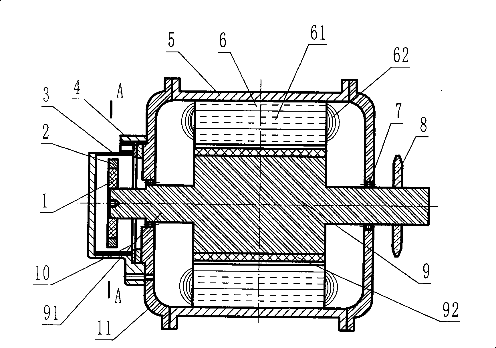
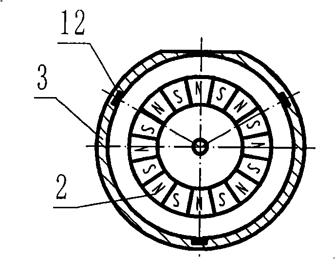
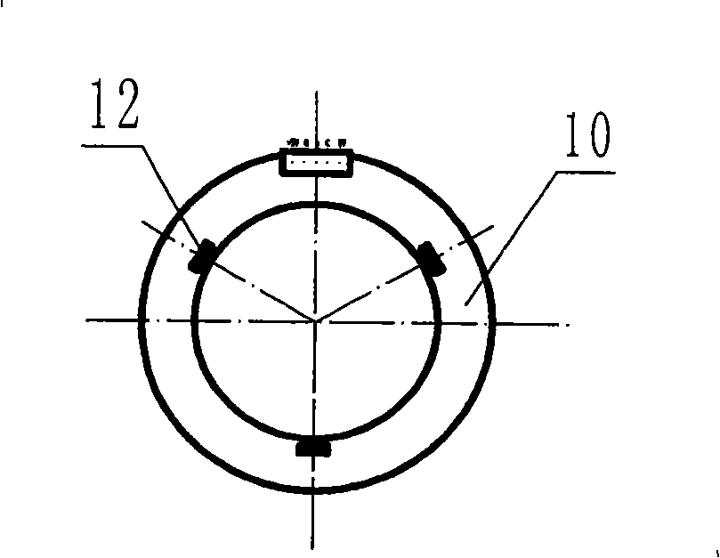
[0034] see Figure 1 ~ Figure 4 , the permanent magnet brushless motor placed separately from the Hall position sensor and the motor stator, including the permanent magnet rotor 9 of the motor, the motor stator 6, the motor shaft 91, the motor housing 5, the Hall position sensor 12 and the controller (not shown in the figure ), and a hall position sensor commutation sensing device placed separately from the motor stator 6, the device is provided with: a permanent magnet commutation rotor 1 and a matching commutation hall position sensor bracket 3, the permanent The magnetic commutation rotor 1 is connected and synchronized with the permanent magnet rotor 9 of the motor, the Hall position sensor bracket 3 is fixedly connected with the motor stator 6, and the Hall position sensor 12 is fixed on the Hall position sensor bracket 3 to be connected with the permanent magnet commutation The corresponding phase position of rotor 1. The permanent magnet commutation rotor 1 corresponds...


PUM


Abstract

The invention provides a permanent-magnetic brushless motor, the Hall position sensor and the motor stator of which are separately positioned. The brushless motor of the invention pertains to technical filed of motors, is characterized by being provided with a phase-change sensing device of the Hall position sensor separately positioned with the motor rotor and has the structure that: a permanent-magnetic phase-change rotor and a phase-change Hall position sensor support which is matched with the rotor are arranged; the permanent-magnetic phase-change rotor and the motor permanent-magnetic rotor are connected with each other and synchronized; the Hall position sensor support and the motor stator are fixedly connected; the Hall position senor is fixedly arranged at the phase position the Hall position sensor support, which is opposite to the permanent-magnetic phase-change rotor. The invention is characterized by effectively preventing the damage to the Hall position sensor caused by overheating, thereby greatly reducing the repair rate of the brushless motor, improving working efficiency, causing the repairing to be more convenient, flexible and fast with low cost and having long service life. In addition, the brushless motor of the invention can be applied to various motors.

Description

technical field [0001] The invention relates to the technical field of electric motors. Background technique [0002] Because the brushless motor replaces the carbon brush and commutator in the brush motor with the Hall position sensor, it avoids the wear of the carbon brush inside the motor, thus greatly extending the life of the motor. But the current brushless motor also has its fatal weakness, that is, the Hall position sensor is placed inside the motor, and even most of them are placed directly on the stator core, or in the gap between the iron core and the wire package, as shown in the attached picture Figure 13 , 14 shown. Although such a structure is simple, it has great hidden dangers. Since the stator wire pack generates a lot of heat during operation, the heat is directly conducted to the Hall sensor. As a semiconductor integrated circuit, the Hall sensor has a certain limit of temperature resistance (-55~150°C), the temperature of the motor will rise cumulati...

Claims


Application Information

Patent Timeline
IPC IPC(8): H02K29/08H02K11/00H02K11/215
Inventor 刘卫东刘继武
Owner 刘卫东
Why Eureka
Try Eureka