Plate lifting device for PCB plate

A PCB board and bottom board technology, which is applied in the field of PCB board lifting device, can solve the problems of PCB board soldering quality cannot be guaranteed, sharpening, etc., and achieve the effect of facilitating automatic large-scale production and simple structure

Inactive Publication Date: 2008-10-29
SUZHOU MINGFU AUTOMATIC SCI & TECH
View PDF0 Cites 0 Cited by
  • Summary
  • Abstract
  • Description
  • Claims
  • Application Information

AI Technical Summary

Problems solved by technology

[0002] When the soldering operation of the PCB board is finished and the board is lifted, the PCB is usually kept in a horizontal state and raised upwards to lift the board. When the board is lifted in this way, there will be undesirable phenomena such as sharpening, less tin, and empty soldering, which will not affect the soldering quality of the PCB board. ensure

Method used


Image

  • Plate lifting device for PCB plate
  • Plate lifting device for PCB plate

Examples


Embodiment Construction

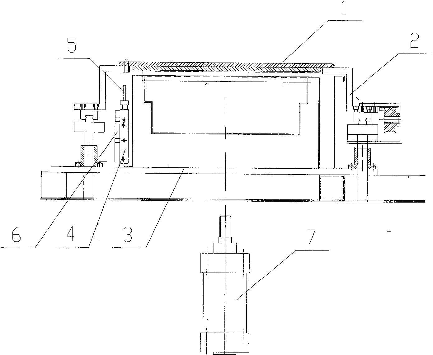
[0012] like figure 1 A PCB board lifting device shown has a jig 1 for clamping the PCB board and a support 2 for supporting the jig 1. The support 2 is fixedly installed on the bottom plate 3 below, on one side of the bottom plate 3 A board lifting cylinder 4 is fixedly installed, and when the push rod 5 of the board lifting cylinder 4 rises, it is offset against the lower edge of one side of the clamp 1, and a jacking cylinder 7 is arranged below the clamp. In addition, in order to facilitate the installation and position adjustment of the lifting cylinder, a cylinder mounting seat 6 is fixedly arranged on the bottom plate 3 , and the lifting cylinder 4 is connected to the cylinder mounting seat 6 .

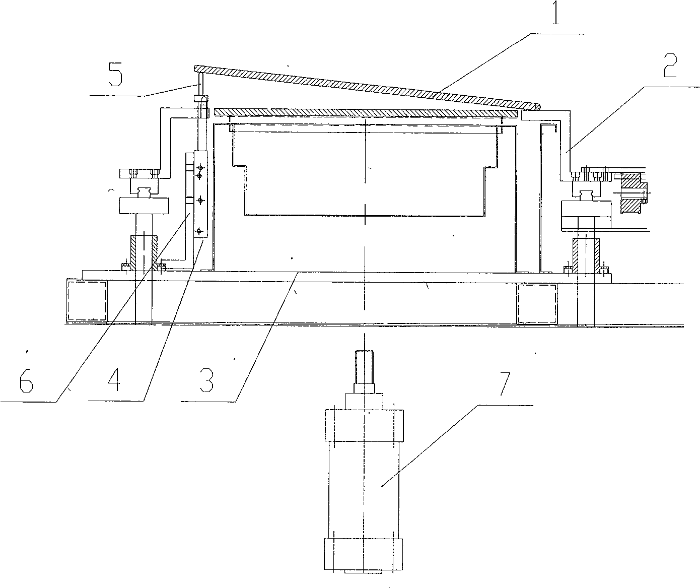
[0013] When in use, after the PCB board clamped by the fixture 1 has been welded, first start the lifting cylinder 4, and the ejector rod 5 of the lifting cylinder 4 lifts up the lower edge of one side of the fixture 1 to make the fixture 1 tilt, as figure 2 As shown, in order...


PUM


Abstract

The invention relates to a device of a solder pot, in particular to a PCB board removing device which comprises a clamp used for clamping the PCB board, and a support used for supporting the clamp. The support is fixedly mounted on a motherboard at the lower part; a board removing cylinder is fixedly mounted at one side of the motherboard; when the mandril of the board removing cylinder is upraised, the mandril is butted against the lower edge of one side of the clamp; a lifting cylinder is arranged at the lower part of the clamp, and a cylinder mounting base is fixedly arranged on the motherboard; the board removing cylinder is connected with the cylinder mounting base. The PCB board removing device of the invention has simple structure, by imitating the welding process of WAVE SOLDING, a side angle is generated when removing the PCB board so that detinning is carried out at one angle when tin-soldering is finished by the PCB elements, thus solving the phenomena of poor welding such as icicles, insufficient solder and missing solder, etc. The PCB board removing device of the invention is beneficial to automated large scale production.

Description

technical field [0001] The invention relates to a solder furnace device, in particular to a PCB lifting device. Background technique [0002] When the soldering operation of the PCB board is finished and the board is lifted, the PCB is usually kept in a horizontal state and raised upwards to lift the board. When the board is lifted in this way, there will be undesirable phenomena such as sharpening, less tin, and empty soldering, which will not affect the soldering quality of the PCB board. ensure. Contents of the invention [0003] In order to fundamentally solve the adverse phenomena caused by improper de-tinning of the above-mentioned PCB during the soldering process, the present invention provides a PCB board lifting device. [0004] The technical solution adopted by the present invention to solve the technical problem is: a PCB board lifting device, which has a clamp for clamping the PCB board and a support for supporting the clamp, and the support is fixedly install...

Claims


Application Information

Patent Timeline
Patent Type & Authority Applications(China)
IPC IPC(8): H05K3/34
Inventor 庄春明
Owner SUZHOU MINGFU AUTOMATIC SCI & TECH
Why Eureka
Try Eureka