Circuit board bearing device and circuit board fixing method

A technology of a bearing device and a fixing method, which is applied in the direction of assembling printed circuits, electrical components, and electrical components with electrical components, can solve the placement error of solder paste printed graphic devices, poor connection between electronic components and circuit boards, and electronic components. Device damage, falling off and other problems, to achieve the effect of large contact surface, excellent placement effect, and warpage prevention

Inactive Publication Date: 2008-10-29
AVARY HLDG (SHENZHEN) CO LTD +1
View PDF0 Cites 0 Cited by
  • Summary
  • Abstract
  • Description
  • Claims
  • Application Information

AI Technical Summary

Problems solved by technology

[0005] Since the various electronic components on the mounted surface have different shapes and sizes, and the carrying tray is flat, the circuit board that has been mounted on one side is prone to shift and shake when placed on the carrying tray, resulting in surface Errors in solder paste printing graphics and device placement during mounting,

Method used


Image

  • Circuit board bearing device and circuit board fixing method
  • Circuit board bearing device and circuit board fixing method
  • Circuit board bearing device and circuit board fixing method

Examples


Embodiment Construction

[0022] The implementation of the technical solution will be further described in detail below in conjunction with the accompanying drawings.

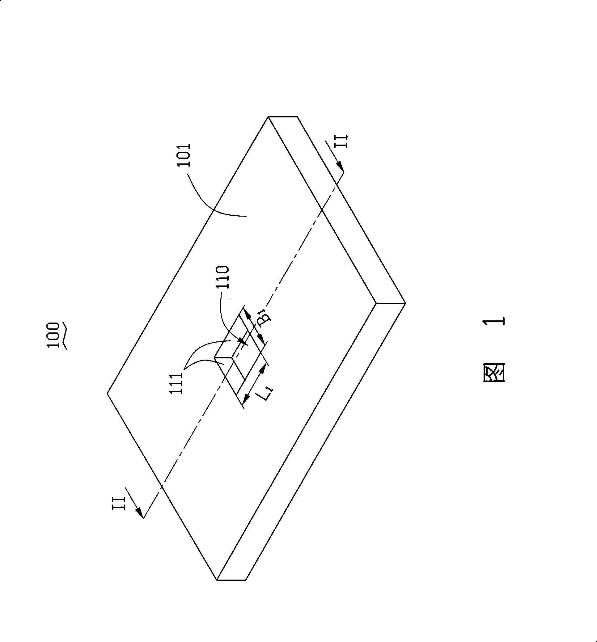
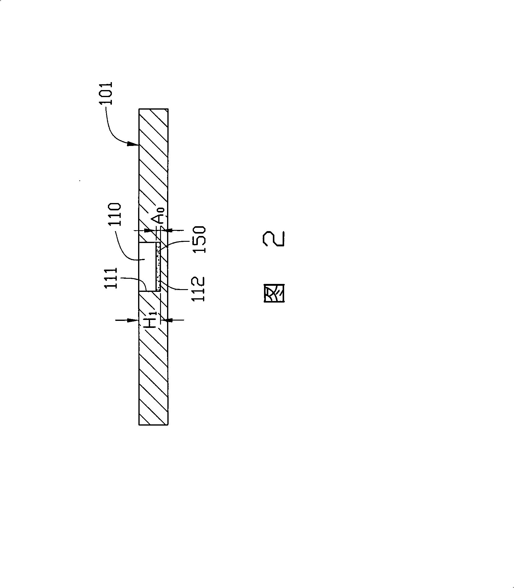
[0023] Please refer to FIG. 1 and FIG. 2 , the circuit board carrying device 100 provided by the first embodiment of the technical solution has a carrying surface 101 for carrying a circuit board. The bearing surface 101 is provided with at least one groove 110, and the groove 110 is used for accommodating electronic components arranged on the first surface of the circuit board. Therefore, the structure of the groove 110 is compatible with the structure of the electronic components. The so-called matching means that the electronic components can be accommodated in the groove 110 exactly. The groove 110 is surrounded by a plurality of side surfaces 111 and a bottom surface 112 . The bottom surface 112 of the groove 110 is provided with an adhesive layer 150 for bonding and fixing the electronic components accommodated in the groove 110 ...


PUM


Abstract

The invention provides a circuit board bearing device which is provided with a bearing surface used for bearing the circuit board. The bearing surface is provided with at least one groove which is provided with a groove bottom surface opposite to the bearing surface; the groove bottom surface is provided with a bonding layer. The technical proposal also provides a method for fixing the circuit board. In the technical proposal, the circuit board can be stably fixed on the circuit board bearing device, and the situation of stress concentration can not occur on electronic components adhered on the surface of the circuit board.

Description

technical field [0001] The invention relates to circuit board placement technology, in particular to a circuit board carrying device and a circuit board fixing method. Background technique [0002] With the development of electronic products in the direction of miniaturization, functional diversification, and circuit precision, Surface Mounted Technology (SMT) has also developed from single-sided mounting to double-sided mounting to meet the assembly requirements of electronic products. . [0003] The single-sided mounting process of the circuit board is to fix one side of the circuit board on the carrier tray to prevent the circuit board from shifting during the surface mounting process, and then perform solder paste printing, device placement, reflow soldering, etc. on the other side of the circuit board step. Among them, solder paste printing refers to printing solder paste on the pads on the surface of the circuit board through a template with a predetermined pattern, ...

Claims


Application Information

Patent Timeline
IPC IPC(8): H05K13/00H05K3/30
Inventor 郝建一
Owner AVARY HLDG (SHENZHEN) CO LTD
Why Eureka
Try Eureka