
Liquid phase cascade rectification device for isotope separation

A technology of isotope separation and liquid phase, which is applied in the field of liquid phase cascading rectification devices, can solve the problems of affecting separation efficiency, reduction of feed liquid concentration, and inconsistency, so as to save energy, ensure separation efficiency, and avoid back mixing.

Active Publication Date: 2008-11-05
JIANGSU HUAYI TECH
View PDF0 Cites 7 Cited by
  • Summary
  • Abstract
  • Description
  • Claims
  • Application Information

AI Technical Summary

Problems solved by technology

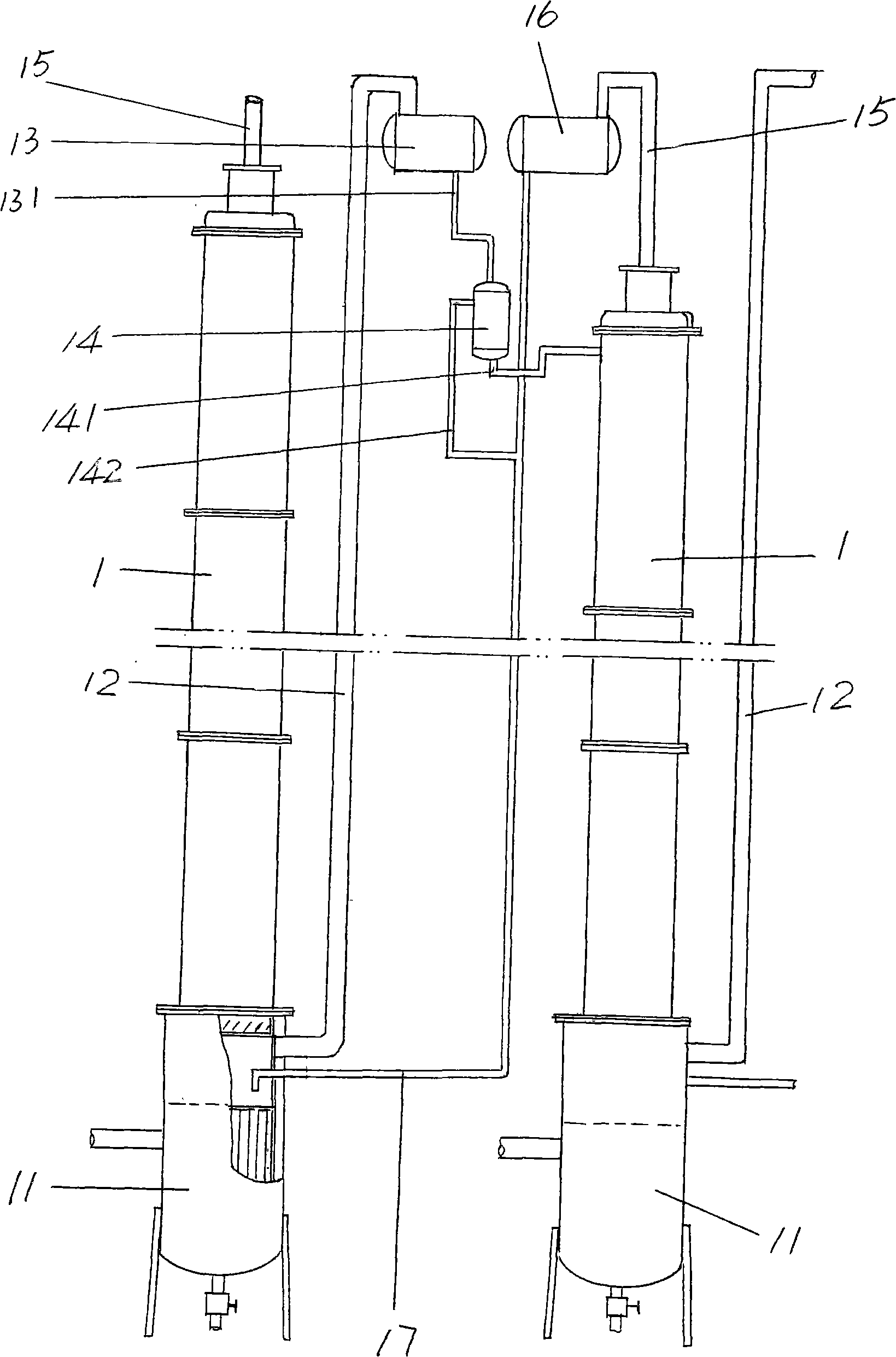
[0005] In addition, the above-mentioned device also has the following disadvantages, that is, the liquid returned to the rectifying tower 1 of the previous stage by the return pipe 17 will be mixed with the liquid flowing down in the rectifying tower 1 of the previous stage, That is, the two phases are mixed in the bottom of the rectification tower 1, so that the concentration of the feed liquid at the top of the rectification tower 1 in the next stage is reduced, which affects the separation efficiency
Because the concentration of the return liquid of the rectifying tower 1 of the previous stage is the same as the concentration of the gaseous phase at the top of the rectifying tower 1 of the latter stage, and what flows into the rectifying tower 1 of the latter stage is The liquid condensed by the first overhead condenser 13 of the rectifying tower 1 is actually similar to the liquid phase concentration of the phase equilibrium, so the concentration of the two is different. It is often ignored because it is harmless, but isotope rectification separation is not the case, because the change of the liquid concentration at the top of the rectification tower 1 will directly affect the separation efficiency of the rectification tower

Method used


Image

  • Liquid phase cascade rectification device for isotope separation
  • Liquid phase cascade rectification device for isotope separation
  • Liquid phase cascade rectification device for isotope separation

Examples


Embodiment Construction

[0021] In order to make the examiners of the patent office, especially the public, understand the structural essence and beneficial effects of the present invention more clearly, the specific implementation of the present invention is described in detail below in conjunction with the accompanying drawings and embodiments, but the description of the embodiments does not constitute For the limitation of the technical solution of the present invention, any formal but not substantive equivalent replacement or conceptual change shall be regarded as the scope of the technical solution disclosed and claimed in the present invention.

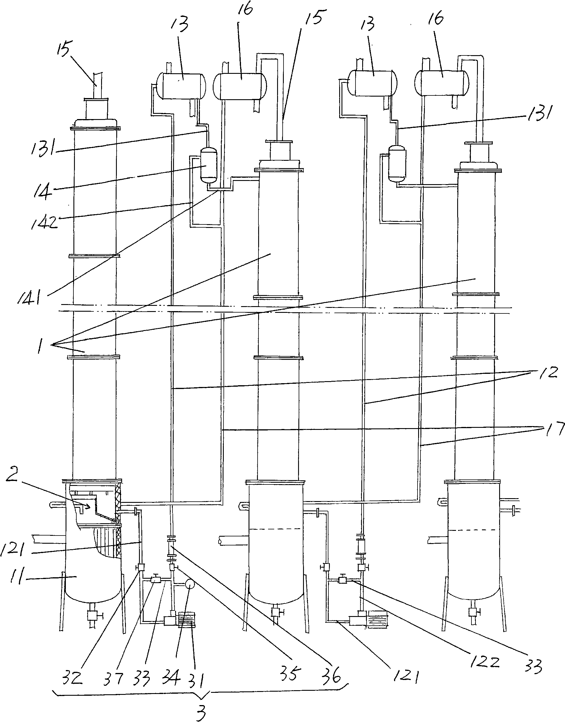
[0022] Please refer to figure 2 , a group of rectification towers 1 for isotope separation rectification, that is, separation of rectification oxygen octadecanoate from natural water, is given, although only a group of rectification towers that are three in number and connected to each other are shown in the figure 1, but the number is obviously not li...


PUM


Abstract

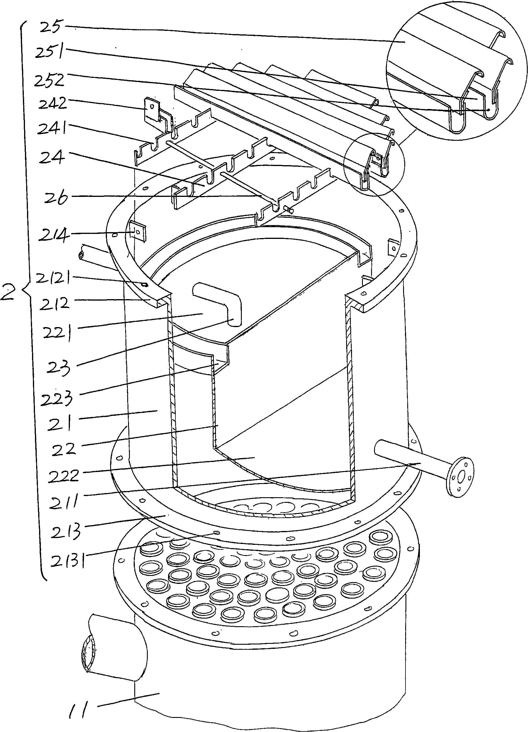
The invention discloses a liquid phase cascade rectifying device for isotope separation, which pertains to the technical field of separation and rectification equipment. The rectifying device comprises a group of rectifying towers which are mutually connected through pipes and each rectifying tower comprises a bottom reboiler, a first pipe, a first overhead condenser, a second overhead condenser, a liquid storage tank, a vapor pipe and a reflux pipe. The rectifying device is characterized in that: the first pipe is provided with a liquid circulating mechanism which is applied to leading liquid from a previous stage of rectifying tower to the top of a next stage of rectifying tower; a catch mechanism which is used for separating the liquid which is in the next stage of rectifying tower and led into by the reflux pipe from the liquid fell from the previous stage of rectifying tower is arranged at the lower part of the rectifying tower and the corresponding upper part of the bottom reboiler. The device has the advantages of being conducive to saving energy and guaranteeing separation efficiency.

Description

technical field [0001] The invention belongs to the technical field of separation and rectification equipment, and in particular relates to a liquid-phase cascade rectification device for isotope separation. Background technique [0002] Isotope separation, such as double-labeled water obtained by separating natural water through rectification, because hydrogen has two stable isotopes in nature, namely: 1 H(protium) and 2 H (deuterium); oxygen has three stable isotopes: 16 O (oxygen sixteen), 17 O (oxygen seventeen) and 18 O (oxygen eighteen). Water composed of dihydrogen and oxygen has nine stable isotope molecules, which exist in natural water in different proportions. Due to the extremely small difference in isotope molecules, separation is very difficult. When separating by rectification, a large number of theoretical plates is often required to purify isotope products. At present, the authoritative report on the packing in the rectification column is that the numb...

Claims


Application Information

Patent Timeline
IPC IPC(8): B01D59/04B01D3/16
Inventor 余兆钧徐志红杨远辉
Owner JIANGSU HUAYI TECH
Learn More