Magnetic punching machine

A technology of punching and magnetic force, which is applied in the field of permanent magnet and electromagnetic composite punching, can solve the problems of extra current loss, large magnetic resistance, etc., and achieve the effect of increasing frequency, high efficiency, and slowing down the accumulation of Joule heat

Inactive Publication Date: 2008-11-05
刘新广
View PDF1 Cites 13 Cited by
  • Summary
  • Abstract
  • Description
  • Claims
  • Application Information

AI Technical Summary

Problems solved by technology

However, the magnetic permeability of the permanent magnetic ring 14 is very close to that

Method used


Image

  • Magnetic punching machine
  • Magnetic punching machine
  • Magnetic punching machine

Examples


specific Embodiment approach 1

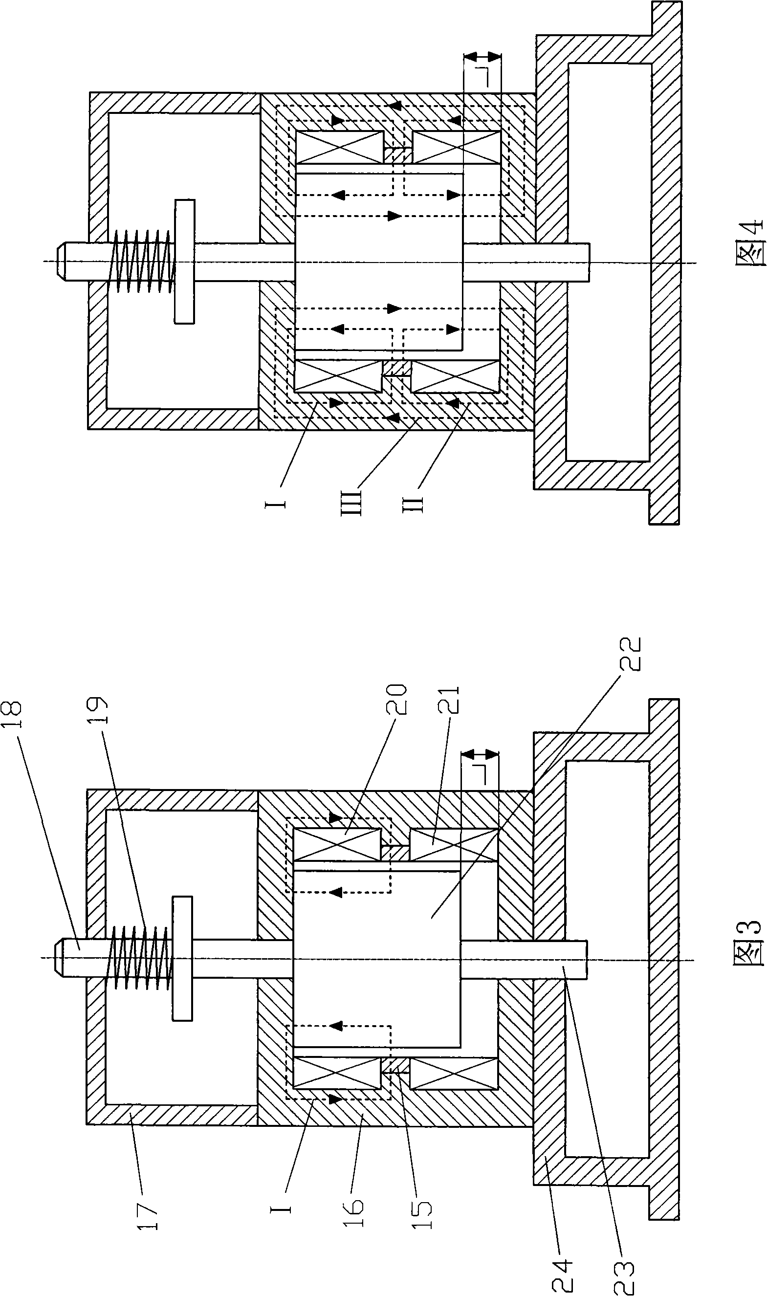
[0042] Specific embodiment one: as shown in Figure 3, on the base 24, the magnetic permeable cylinder 16 is fixed, the magnetic permeable cylinder 16 is wrapped with the upper coil 20, the radially magnetized permanent magnet ring 15, and the lower coil 21, and the moving iron core 22 is placed on them Among them, the axial length dimension of the moving iron core 22 is one stroke (L) shorter than that of the magnetic permeable cylinder 16, and there is a small gap between the outer circle of the moving iron core 22 and their inner circles, and the punch 23 and the guide rod 18 are all affixed with moving iron core 22, and above-mentioned each parts are all coaxial; Pressure spring 19 is enclosed within outside guide bar 18, and the free length of pressure spring 19 is the half of moving iron core 22 strokes (L), i.e. L / 2, The bracket 17 is fixed on the end face of the magnetic tube 16 or other parts of the bed of the punching machine. The punch 23 and the guide rod 18 form a s...

specific Embodiment approach 2

[0043] Specific embodiment two: as shown in Figure 7, the permanent magnetic ring 15 and the magnetic permeable cylinder 16 in the specific embodiment one are changed into the permanent magnetic ring 25 and the magnetic permeable cylinder 26 respectively, and the magnetic permeable lining ring 27 is added, and the others remain unchanged .

specific Embodiment approach 3

[0044] Specific embodiment three: as shown in Figure 8, the spring 19 in specific embodiment one or specific embodiment two is removed, and guide rod 18, support 17 are respectively changed into punch 31, the support 29 that is fixed with base 24, just Become a double-punch punching machine, the punch (not shown) connected to the punch 23 corresponds to the die 28, the punch (not shown) connected to the punch 31 corresponds to the die 30, and the others are unchanged, such a punch It has fully exerted its effectiveness and is extremely efficient.


PUM


Abstract

The invention provides a magnetic punch; a base is fixed with a magnetic-conductive cylinder which is internally covered by an upper coil, a permanent magnetic ring with magnetism charged in the radial direction, and a lower coil; a movable iron core is arranged among the upper coil, the permanent magnetic ring and the lower coil; a non-magnetic punching head and a non-magnetic guide rod are fixedly connected with the movable iron core; a pressure spring is sheathed outside the guide rod; the lower coil is electrified, and the generated electric flux, permanent flux and spring reaction force lead the movable iron core to acceleratively punch downwards to punch a workpiece; subsequently, the power of the lower coil is cut off and the upper coil is electrified, and the generated electric flux and the permanent flux lead the movable iron core to acceleratively punch upwards to an upper dead point, and the spring is compressed to stores energy. As the permanent magnetic ring and the coils are arranged, the working current is greatly reduced, workpiece punching frequency and working efficiency are improved, a control system is simplified, energy consumption is reduced, and service life is prolonged. A hammer head is arranged on the punching head so as to lead the magnetic punch to be used as a forging machine and a crushing machine; a vibration head or a vibration disc is arranged on the punching head or the guide rod so as to lead the magnetic punch to be used as the vibration equipment.

Description

technical field [0001] The invention relates to a punching machine, in particular to a permanent magnet and electromagnetic composite punching machine. Background technique [0002] Traditional mechanical punches driven by electric motors are bulky, cumbersome, and inefficient, and are not easy to realize automation. The development trend is that electromagnetic punches gradually eliminate traditional mechanical punches. As shown in Fig. 1, it is a typical structural schematic diagram of an existing electromagnetic punching machine. Fix the magnetic tube 2 on the base 10, the magnetic tube 2 wraps the coil 3, the coil 3 surrounds the moving iron core 4 with gaps, the punch 1 and the guide rod 9 are fixedly connected with the moving iron core 4; the guide rod of the pressure spring 8 6 is fixed on the end surface of the cylinder 2 or on the bed body, the other end of the guide rod 6 is connected by the connecting plate 7, and the pressure plate 5 is fixed with the guide rod ...

Claims


Application Information

Patent Timeline
IPC IPC(8): B30B1/42
CPCB30B1/42
Inventor 刘新广
Owner 刘新广
Why Eureka
Try Eureka