Lever type pneumatic pressurizing cradle

A pneumatic pressurization and lever-type technology, which is applied in the direction of textiles and papermaking, drafting equipment, spinning machines, etc., can solve the problem of inaccurate upper roller bearing axial centering limit, imperfect spinning supporting functions, and working pressure. Problems such as inconsistency in direction can be solved to achieve the effect of consistent part size, improved stress condition, and stable assembly quality

Inactive Publication Date: 2008-11-05
四川成发普睿玛机械工业制造有限责任公司
View PDF3 Cites 5 Cited by
  • Summary
  • Abstract
  • Description
  • Claims
  • Application Information

AI Technical Summary

Problems solved by technology

In order to improve the use accuracy and interchangeability of the cradle and improve the parallelism between the three rows of top roller bearings, people have continuously improved the lever-type pneumatic pressurized cradle (for example, Chinese patents ZL 01256739.6, ZL 200620035963.6, ZL200720081147.3 etc.), but the existing lever-type pneumatic pressurized cradle still has the following problems: 1. During pressure regulation, the positioning protrusions installed on the lower deck and the positioning holes on the holding tube are prone to interference; 2. The upper roller The axial centering limit of the bearing is not accurate, and the left and right displacement is too large; 3. The bearing direction of the support pad of the top roller bearing is inconsistent with the working pressure direction of the top roller bearing; 4. The alignment of the rear top roller bearing is inconvenient when adjusting the distance. Affect the accuracy of alignment; 5. The supporting function of spinning is not perfect

Method used


Image

  • Lever type pneumatic pressurizing cradle
  • Lever type pneumatic pressurizing cradle
  • Lever type pneumatic pressurizing cradle

Examples


Embodiment Construction

[0030] The structure of the lever type pneumatic pressurized cradle of the present invention will be further described below in conjunction with the accompanying drawings.

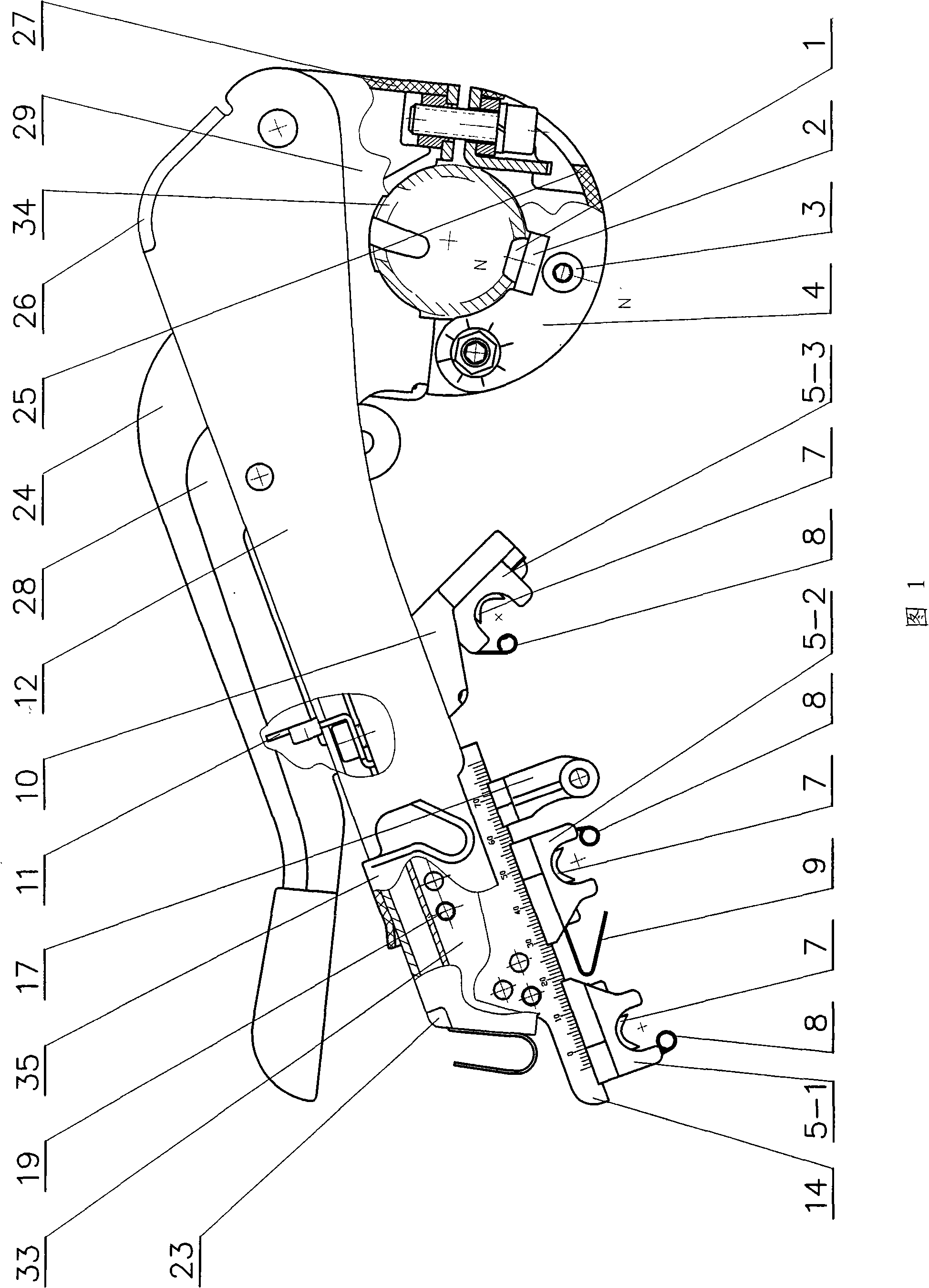
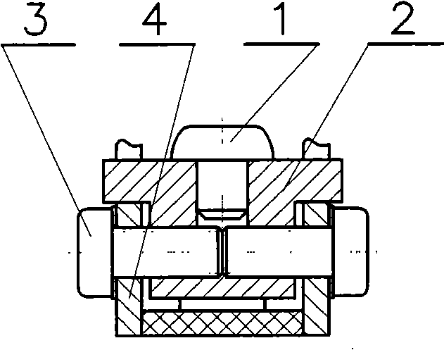
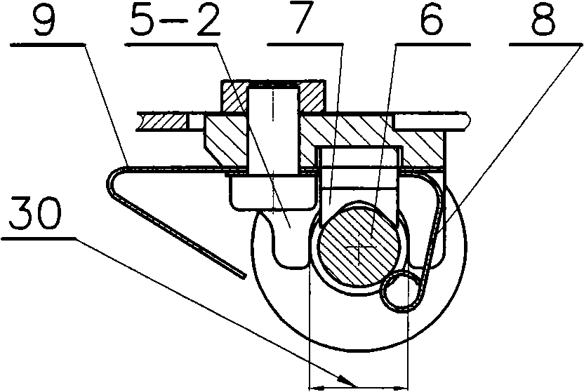
[0031] As shown in Figure 1, the lever-type pneumatic pressurized cradle in this embodiment includes a housing 12, a groove seat 33 hinged with the housing through a pin 19, and an adjustment seat 14 hinged with the groove seat, fixed on the groove seat The rear roller seat 10 on the top, the front bearing seat 5-1 and the middle bearing seat 5-2 installed on the adjustment seat, the rear bearing seat 5-3 installed on the rear roller seat, the handle 28 hinged with the housing and Upper deck 29, one end is hinged with the upper deck, the lower deck 4 that one end is threadedly connected with the upper deck, the holding tube 34 that is equipped with an air bag clamped by the upper deck 29 and the lower deck 4; The overall shape is arc-shaped and streamlined, using plastic fasteners I23, plastic fasteners II...


PUM


Abstract

The invention relates to a lever pneumatic pressing cradle, comprising a casing, a groove seat articulated with the casing, a regulating seat articulated with the groove seat, a back-roller seat fixed on the groove seat, a front bearing seat and a middle bearing seat which are arranged on the regulating seat, a back bearing seat arranged on the back-roller seat, a handle and an upper clamp seat which are articulated with the casing, a lower clamp seat provided with one end articulated with the upper clamp seat and the other end is connected with the upper clamp seat by a thread and a holding tube held by the upper clamp seat and the lower clamp seat. A sphere positioning hole is arranged on the holding tube, and a universal rotary-connection can be formed between the sphere positioning hole of the holding tube and a sphere positioning projection block in the cradle positioning structure so as to avoid the interference to pressure regulation. A V-shaped support cushion used for carrying out radial self-dimensional alignment to a journal of an upper roller bearing and a clip used for carrying out radial positioning and alignment to the journal end face of the upper roller bearing are arranged on the front, middle and back bearing seats so as to largely enhance the stability of the three-line parallelism of the cradle and to effectively reduce the pressure difference between a left ingot and a right ingot so as to enhance the stressing condition of the bearing seats. Moreover, various spinning accessories are arranged on the cradle.

Description

technical field [0001] The invention belongs to textile machinery, in particular to a pneumatically pressurized cradle of a spinning machine. Background technique [0002] The pneumatic pressure cradle is an important part of the spinning machine. The lever type pneumatic pressure cradle is mainly composed of a shell, a groove seat hinged with the shell, an adjustment seat hinged with the groove seat, and a Rear roller housing, front bearing housing and middle bearing housing installed on the adjustment seat, rear bearing housing installed on the rear roller housing, handle and upper card base hinged with the shell, lower card hinged with the upper card base The seat, the holding tube with the air bag clamped by the upper deck and the lower deck, the rotatable roller mounted on the handle, and the pressure transmission crank hinged with the upper deck and assembled with the roller are formed. In order to improve the use accuracy and interchangeability of the cradle and impr...

Claims


Application Information

Patent Timeline
Patent Type & Authority Applications(China)
IPC IPC(8): D01H5/52D01H5/56D01H5/60
Inventor 张子馨雷文金余刚
Owner 四川成发普睿玛机械工业制造有限责任公司
Why Eureka
Try Eureka