
High speed frictional wear experiment auxiliary device allocated on a lathe

A friction and wear test and auxiliary device technology, applied in the direction of testing wear resistance, etc., to achieve the effects of good adaptability, simple sample requirements and simple structure

Inactive Publication Date: 2008-11-05
NANJING UNIV OF AERONAUTICS & ASTRONAUTICS
View PDF0 Cites 12 Cited by
  • Summary
  • Abstract
  • Description
  • Claims
  • Application Information

AI Technical Summary

Problems solved by technology

[0004] Aiming at the problems existing in the existing friction and wear testing machines, the present invention proposes an auxiliary device for high-speed friction and wear testing that is installed on a lathe and used with a dynamometer with a simple structure, low cost, and can transfer loads more accurately

Method used


Image

  • High speed frictional wear experiment auxiliary device allocated on a lathe
  • High speed frictional wear experiment auxiliary device allocated on a lathe
  • High speed frictional wear experiment auxiliary device allocated on a lathe

Examples


Embodiment Construction

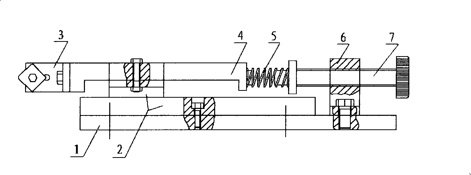
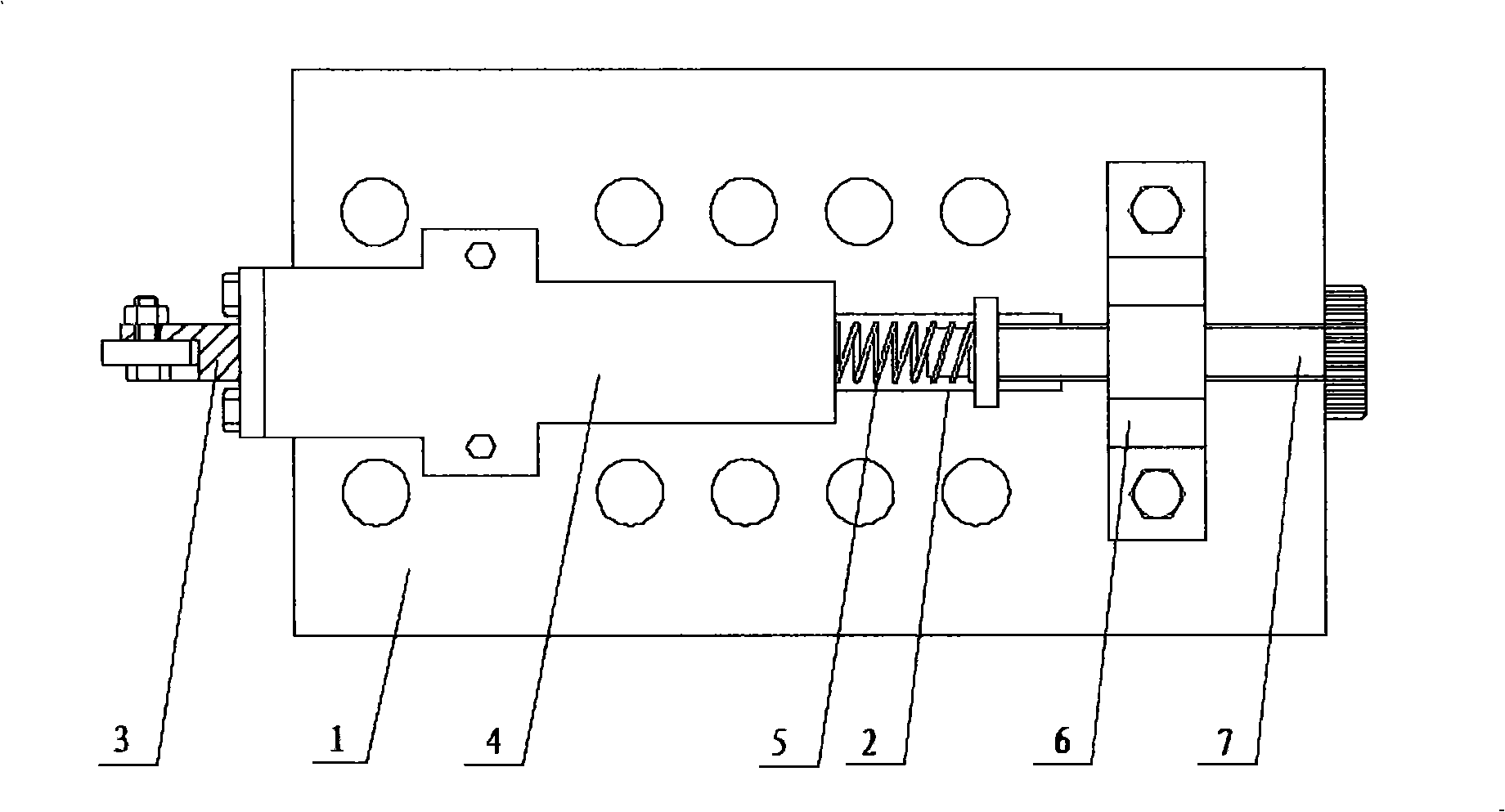
[0013] The present invention is realized through the following measures: the device includes a bottom plate 1, a sliding guide rail pair 2, a chuck 3, and a loading mechanism. The loading mechanism includes an auxiliary body 4 , a spring 5 , a bolt seat 6 and a loading bolt 7 . The uses and features are:

[0014] Base plate 1 is the base of the device, and there are bolt connection holes above, which can be fixed on the three-way dynamometer with bolts.

[0015] The sliding guide rail pair 2 is fixed on the bottom plate and is used for accommodating the auxiliary body 4. Since the friction force of the guide rail pair is negligible, the load can be transferred more accurately.

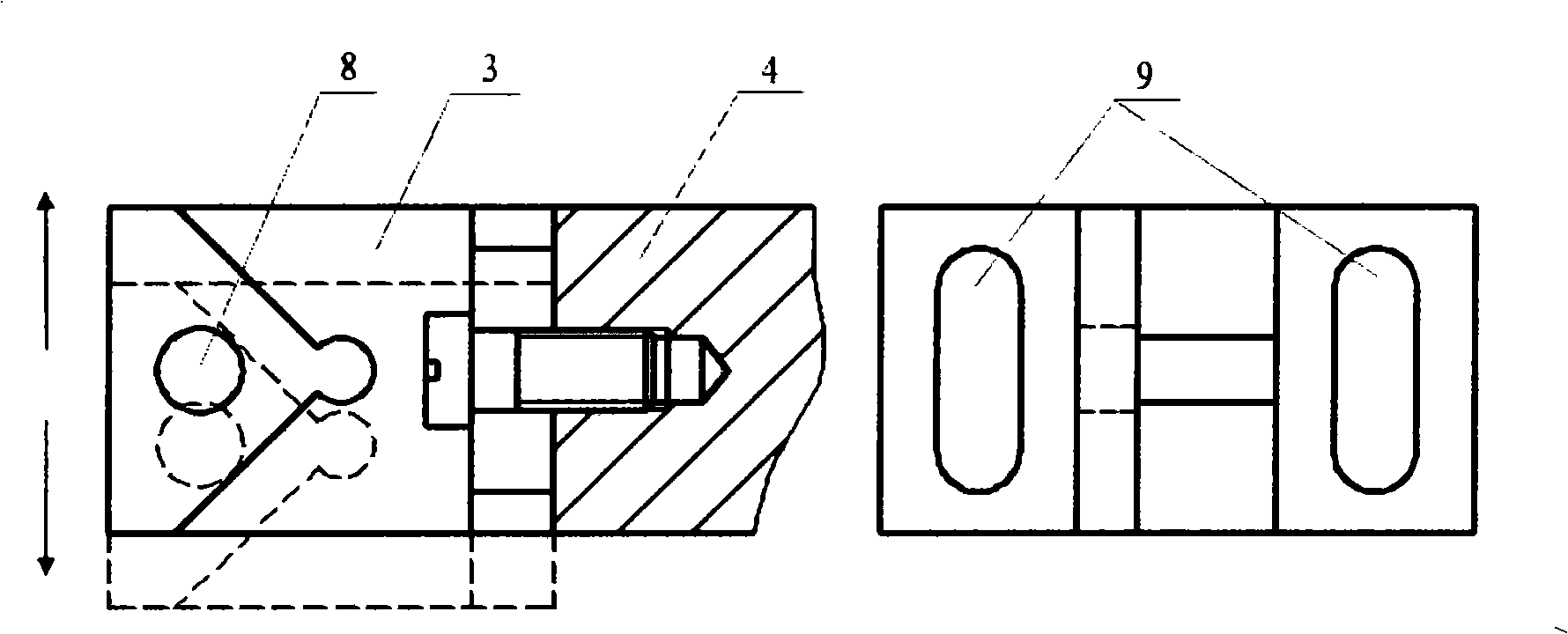
[0016] The chuck 3 is installed on the auxiliary body 4 to hold the sample I12; the shape of the chuck can be designed according to the shape of the sample I12 required for the test. The collet 3 is provided with a positioning groove 9, and the connection position with the auxiliary body 4 can be adj...


PUM


Abstract

The present invention provides a high-speed friction wear test auxiliary device which is provided on a lathe, and belongs to the key device used by friction wear test. The device comprises a baseboard (1) which is provided with a horizontal slide way pair (2) at one end of the baseboard (1). An auxiliary body (4) is fixedly connected with a sliding block of the horizontal slide way pair. One end of the auxiliary body (4) is provided with a clamping head (3) which is used for clamping the sample I (12), and the other end is connected with one end of the horizontal spring (5). The other end of the horizontal spring is connected with a loading bolt (7) which is supported by a bolt base (6) installed on the baseboard (1). The device has the advantages of simple structure and low cost, and can transfer load more accurately.

Description

Technical field [0001] The utility model relates to an auxiliary device for a high-speed friction and wear test configured on a lathe, which belongs to the friction and wear test device. Background technique [0002] At present, the friction and wear test generally carried out on the existing friction and wear testing machine has the disadvantages of large friction vibration and long material pattern preparation period, and the test conditions are affected by the structure of the equipment, and the friction speed can be realized in a small range, which cannot meet the requirements High-speed friction and wear research needs. For example, the MMW-1A universal friction and wear testing machine has a maximum speed of 2000r / min, but the maximum contact diameter of the sample is 46mm, and the maximum achievable sliding speed is 290m / min, and the friction and vibration will stop once the speed is higher than 1000r / min. Quite obviously, it seriously affects the reliability of the ...

Claims


Application Information

Patent Timeline
Patent Type & Authority Applications(China)
IPC IPC(8): G01N3/56
Inventor 李亮何宁卞荣赵威戚宝运杨吟飞王琦田佳
Owner NANJING UNIV OF AERONAUTICS & ASTRONAUTICS
Learn More