
Vehicle-mounted intelligent power management system for CAN bus technology automobile

A technology of CAN bus and intelligent power supply, which is applied in the field of automotive power management system and automotive electronic control, which can solve the problems of high static power consumption, excessive battery discharge, and no monitoring of working status, so as to improve reliability and safety and prevent excessive The effect of discharging and reducing static power consumption

Inactive Publication Date: 2008-11-12
TSINGHUA UNIV
View PDF0 Cites 38 Cited by
  • Summary
  • Abstract
  • Description
  • Claims
  • Application Information

AI Technical Summary

Problems solved by technology

In this traditional power supply mode, the power system has no fault diagnosis for the relay that controls the power line on and off, and the user cannot know the diagnostic information of the relay; the power system has no monitoring function for the working status of the power storage and power supply line. There are no preventive measures for the over-discharge of the battery, so the occurrence of over-discharge of the battery will cause great inconvenience to the user
[0004] In addition, there is no classification of digital electricity in traditional power management. With the continuous increase of vehicle electrical appliances and electronic controllers, the static power consumption of batteries is also increasing. When the car is left standing for a long time, it is easy to cause excessive discharge of the battery.

Method used


Image

  • Vehicle-mounted intelligent power management system for CAN bus technology automobile
  • Vehicle-mounted intelligent power management system for CAN bus technology automobile
  • Vehicle-mounted intelligent power management system for CAN bus technology automobile

Examples


Embodiment Construction

[0024] The vehicle-mounted intelligent power management system proposed by the present invention is described in detail in conjunction with the accompanying drawings and embodiments as follows:

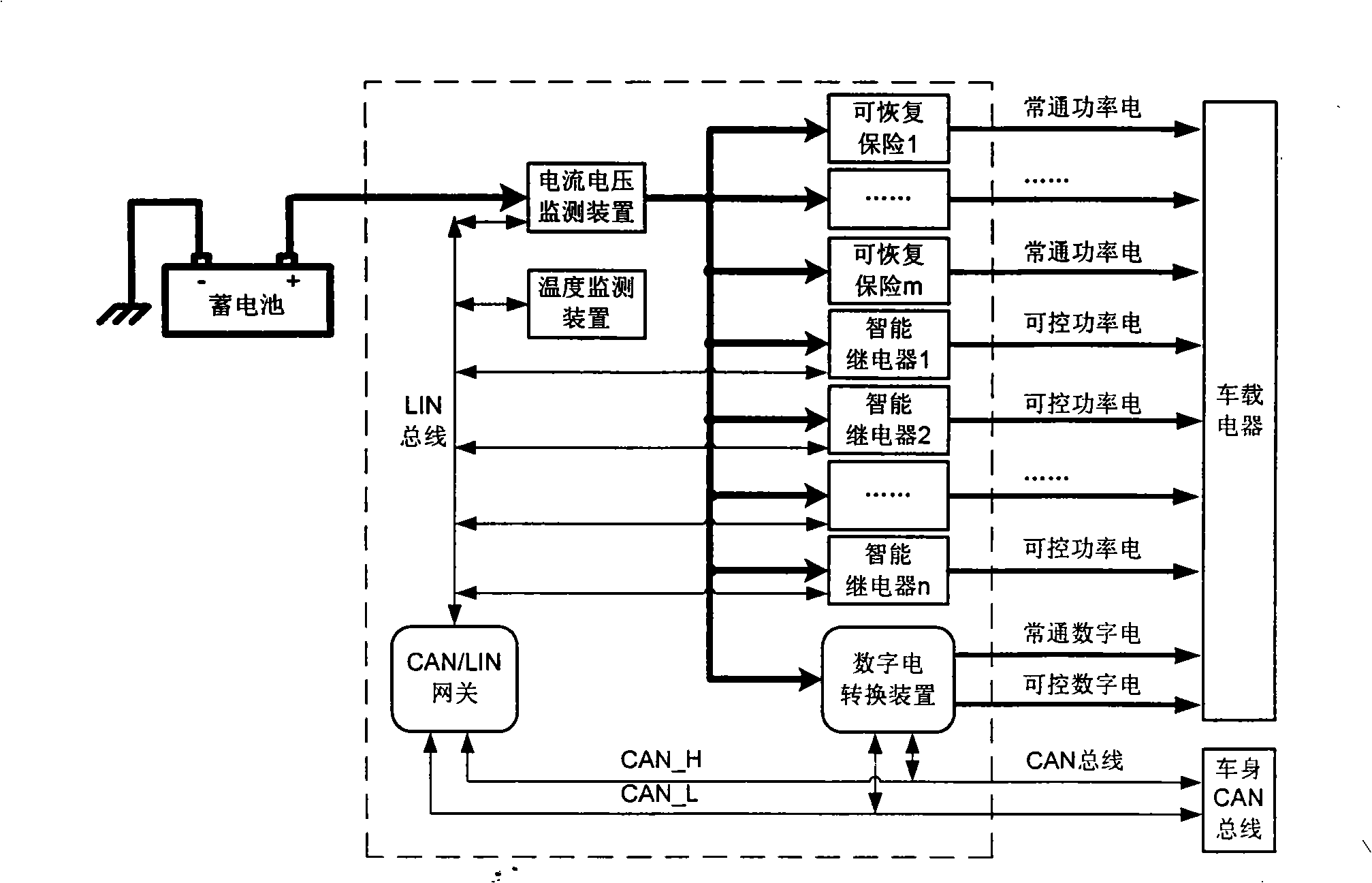
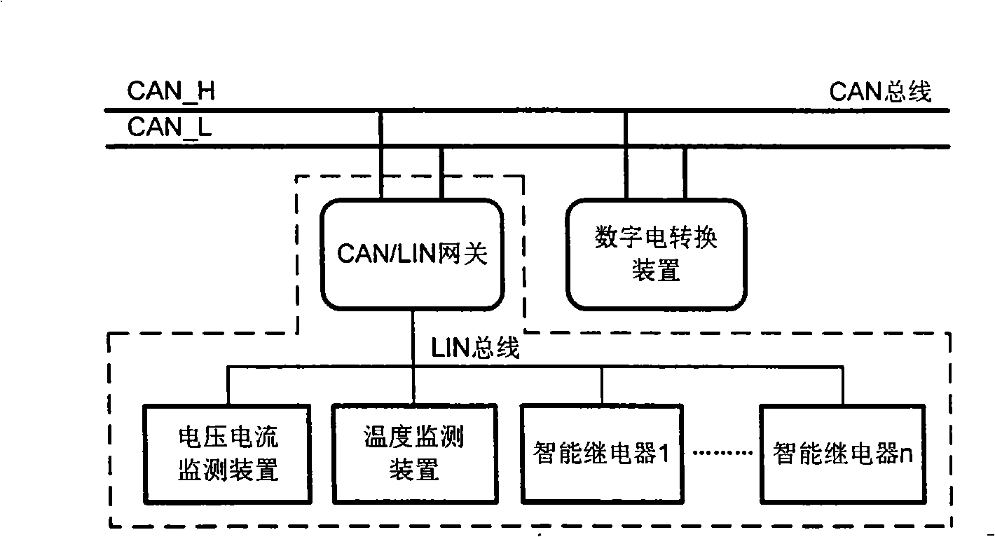
[0025] The vehicle-mounted intelligent power management system that is used for CAN bus technology automobile of the present invention, its overall system structure is as follows figure 1 shown. The system is composed of devices in the dotted box in the figure, including: current and voltage monitoring device, temperature monitoring device, n-way intelligent relay, m-way recoverable insurance, digital power conversion device, and CAN / LIN gateway. (According to the LIN protocol, the maximum value of n is 14; m can be any natural number.)

[0026] The connection between the on-board intelligent power management system and the outside includes: the connection between the input terminal of the system and the positive pole of the battery, and the power is taken from the positive pole of t...


PUM


Abstract

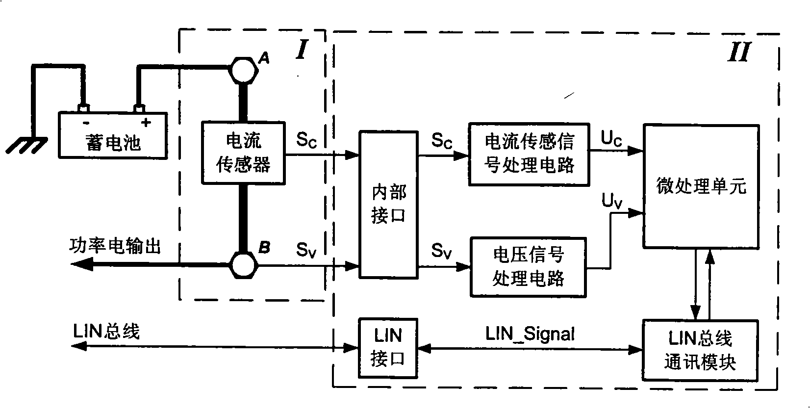
The invention relates to a vehicle-bone intelligent power management system used for CAN bus technology vehicles, belonging to the technical field of electronic vehicle control. The system includes a current and voltage monitoring device, a temperature monitoring device, an n route intelligent relay, an m route restorable fuse, a digital electric converting device and a CAN / LIN gateway; wherein, the input end of the current and voltage monitoring device is directly connected to the anode of a storage cell; the output end of the power electric signal of the current and voltage monitoring device is respectively connected to the input ends of the m route restorable fuse, the n route intelligent relay and the digital electric converting device; the temperature monitoring device is arranged at the proper position of the storage cell; the output end of the communication signals of the current and voltage monitoring device, the temperature monitoring device and the intelligent relay are connected with the CAN / LIN gateway by an LIN bus; the CAN / LIN gateway and the digital electric converting device are directly connected with the CAN bus of the body of the vehicle. The system realizes the on-off control of the power electricity of the vehicle by adopting a digital signal, monitors the sate of the storage cell of the vehicle, prevents the storage cell from over-discharging and reduces the static power consumption of the storage cell.

Description

technical field [0001] The invention belongs to the technical field of automobile electronic control, in particular to an automobile power management system, which is suitable for automobiles using CAN bus technology. Background technique [0002] With the development of automotive electronic and electrical technology, there are more and more electrical equipment on the car, which not only brings ride comfort, but also greatly increases the requirements for power consumption, and accordingly puts forward higher requirements for automotive power management. . [0003] In the prior art, the on-off of the power supply is controlled by the key position of the car power supply, and the on-off action of the power consumption is realized by using a multi-channel electromagnetic relay, and the over-current protection is realized by a blown fuse. When the key gear is turned from OFF to ACC, the main switch relay is closed and supplies power to the body electrical appliances. When t...

Claims


Application Information

Patent Timeline
IPC IPC(8): B60L3/00B60R16/02H04L12/28H04L12/66H02J7/00
CPCY02T90/16
Inventor 连小珉陆良杨殿阁张新丰薛雯郑四发罗禹贡李克强王建强
Owner TSINGHUA UNIV
Learn More