Energy-saving type communication base station square compartment heat radiating device
A heat dissipation device and communication base station technology, applied in the direction of indirect heat exchangers, lighting and heating equipment, etc., can solve problems such as inability to cool, affect environmental protection, and complex structures, and achieve enhanced heat exchange capacity, extended effective time, and scope of application wide range of effects
- Summary
- Abstract
- Description
- Claims
- Application Information
AI Technical Summary
Problems solved by technology
Method used
Image
Examples
Embodiment 1
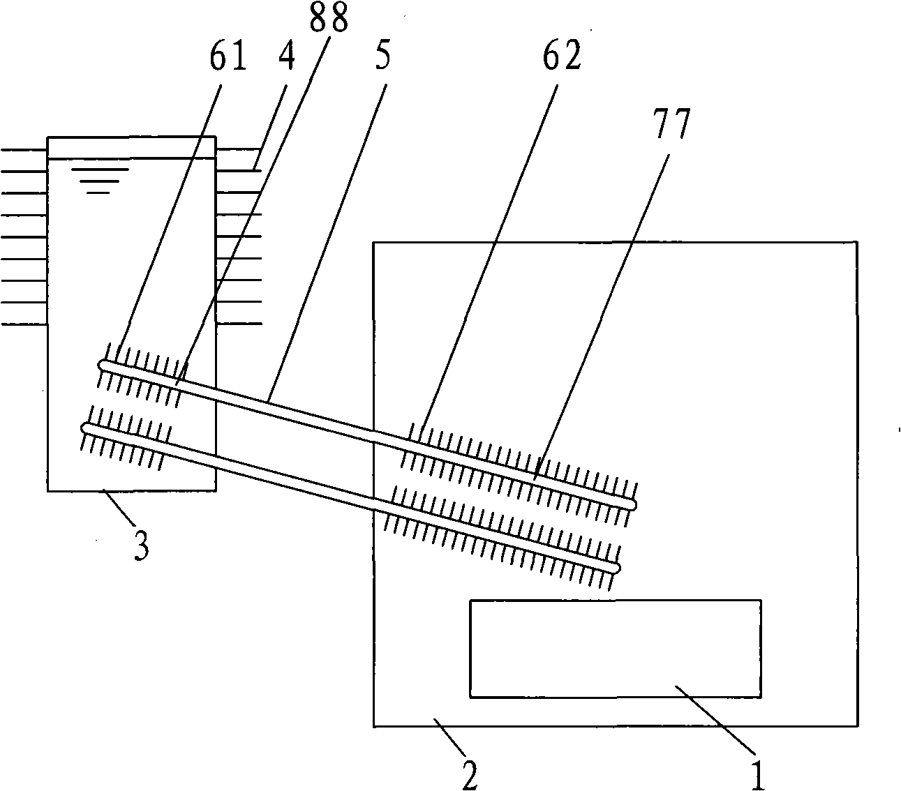
[0024] Embodiment 1: as figure 1 As shown, an energy-saving communication base station shelter cooling device of the present invention includes a heat pipe bundle composed of two heat pipes 5, the evaporation section 77 and the condensation section 88 of the heat pipe 5 are respectively located inside and outside the shelter 2, The working medium in the heat pipe 5 evaporates and absorbs the heat generated by the heat source 1 in the shelter 2 in the evaporation section 77 with fins 62 , and transfers the heat to the condensation section 88 of the heat pipe 5 . A water tank 3 is provided outside the shelter 2, water is housed in the water tank 3, and the condensation section 88 of the heat pipe 5 is placed below the water surface in the water tank 3. In order to enable the water tank 3 to quickly dissipate heat, a heat dissipation device is provided on the outer surface of the top of the water tank 3, and the heat dissipation device is the heat dissipation rib 4 that is locate...
Embodiment 2
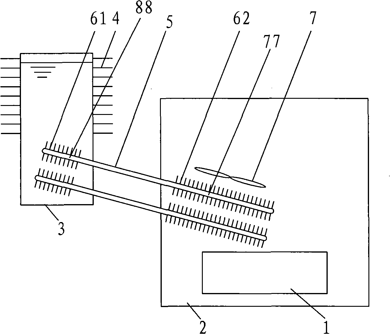
[0028] Embodiment 2: as figure 2 As shown, when the temperature in the shelter 2 is too high and forced heat dissipation is required, the shelter 2 is provided with a fan 7 for increasing the amount of heat exchange between the evaporation section 77 of the heat pipe 5 and the air, and the fan 7 increases the air near the surface of the evaporation section 77. flow, forming forced convection to increase the heat exchange between the heat pipe 5 and the hot air. Other technical schemes are all the same as in Example 1.
Embodiment 3
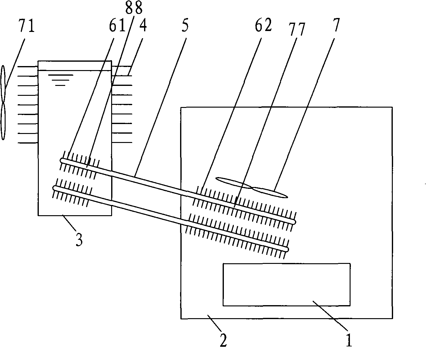
[0029] Embodiment 3: as image 3 As shown, when the temperature in the shelter 2 is too high and forced heat dissipation is required, the shelter 2 is provided with a fan 7 for increasing the amount of heat exchange between the evaporation section 77 of the heat pipe 5 and the air, and the fan 7 increases the air near the surface of the evaporation section 77. flow, forming forced convection to increase the heat exchange between the heat pipe 5 and the hot air. And when the water in the water tank 3 accumulates more heat and needs to dissipate heat quickly to the air in time, a fan 71 for heat dissipation needs to be set up outside the water tank 3, and the fan 71 is opened to speed up the air around the water tank 3 wall surface and the cooling ribs 4. Flow, to achieve the purpose of cooling in time. Other technical schemes are all the same as in Example 1.
PUM
 Abstract
Description
Claims
Application Information
 - R&D
- Intellectual Property
- Life Sciences
- Materials
- Tech Scout
- Unparalleled Data Quality
- Higher Quality Content
- 60% Fewer Hallucinations
Browse by: Latest US Patents, China's latest patents, Technical Efficacy Thesaurus, Application Domain, Technology Topic, Popular Technical Reports.
© 2025 PatSnap. All rights reserved.Legal|Privacy policy|Modern Slavery Act Transparency Statement|Sitemap|About US| Contact US: help@patsnap.com


