Manual laser cursor image positioning apparatus for camera

A cursor and camera technology, applied in the field of optical instruments, can solve problems such as no reports found, and achieve the effect of simple structure and low cost

Inactive Publication Date: 2008-11-12
CHANGCHUN INST OF OPTICS FINE MECHANICS & PHYSICS CHINESE ACAD OF SCI
View PDF0 Cites 2 Cited by
  • Summary
  • Abstract
  • Description
  • Claims
  • Application Information

AI Technical Summary

Problems solved by technology

[0003] After reviewing the information, no relevant information was found

Method used


Image

  • Manual laser cursor image positioning apparatus for camera

Examples


Embodiment Construction

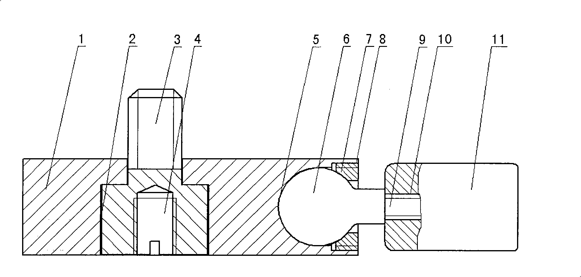
[0009] The invention according to figure 1 The structure shown is implemented, wherein the connecting seat 1, the step hole 2, the ball socket 5 and the pressure ring thread hole 8 are integrated, and the material is cast aluminum or plastic, and the length, width and height dimensions do not exceed the size of the camera body, and the step hole 2 The diameter of is greater than the second-order outer diameter of the camera attachment screw 3 .

[0010] The ball head 6 adopts a spherical shape, and the radius of curvature of the spherical surface contacted by the ball head ring 7 and the ball head socket 5 is the same as that of the ball head 6 . The ball socket 5 cooperates with the ball head 6 and the ball head pressure ring 7 to adopt the sliding damping cooperation, the material of the ball head 6 is stainless steel, the material of the ball head pressure ring 7 is brass, and the laser cursor projector 11 is available in the market. A laser pointer with a ball joint hole....


PUM


Abstract

A manual laser-cursor image location device used in cameras pertains to cursor image location devices of optical instruments. The technical problem to be solved is to provide a manual laser-cursor image location device used in cameras. The manual laser-cursor image location device of the invention comprises a joint base, a step-hole, a camera coupling screw, a bulb, a bulb clamping ring, a laser-cursor balopticon, etc. The step-hole is positioned in the position which is slightly left-skewed in the middle of the joint base; a pit of the bulb and a thread hole of the bulb clamping ring are positioned at the right end of the joint base; a connection screw hole of a tripod is positioned at the center of the bottom of the camera coupling screw; the camera coupling screw runs through the step-hole on the joint base and is then connected with the step-hole by thread; the bulb runs through the thread hole of the bulb clamping ring and extends in the pit of the bulb and the connection between the bulb clamping ring and the thread hole of the bulb clamping ring is threaded connection; between the bulb and the pit of the bulb as well as the bulb clamping ring, rotary and sliding damping contact matching is adopted; the bulb is connected with a connection screw hole of the bulb on the laser-cursor balopticon by a bulb screw; the laser-cursor balopticon rotates internally and slides for damping matching through the pit of the bulb on the joint base.

Description

technical field [0001] The invention belongs to the technical field of optical instruments and relates to a manual laser cursor image positioning device for cameras. Background technique [0002] With the development of the national economy, the progress of society and the improvement of people's living standards, more and more people go out to travel, and taking pictures is the hobby of most tourists. way to take pictures. This requires choosing a location for taking pictures, and only when the location is selected accurately can an ideal photo be taken. If the position is not found correctly, there will be virtual phenomena or the matching between the characters and the background will not be coordinated. [0003] After checking the information, no relevant information was found. Contents of the invention [0004] In order to solve the problem of finding the correct photo position in the Selfie and take an ideal photo, a Selfie station device matching the camera is de...

Claims


Application Information

Patent Timeline
Patent Type & Authority Applications(China)
IPC IPC(8): G03B17/56G03B17/38G02B27/20
Inventor 刘大禹
Owner CHANGCHUN INST OF OPTICS FINE MECHANICS & PHYSICS CHINESE ACAD OF SCI
Why Eureka
Try Eureka