Method and device for manufacture of connecting rod

A connecting rod, connecting hole technology, applied in the direction of connecting rod, shaft and bearing, metal processing, etc., can solve problems such as adverse effects, noise roundness, etc., to achieve the effect of promoting removal or separation

Inactive Publication Date: 2008-11-12
HONDA MOTOR CO LTD
View PDF6 Cites 9 Cited by
  • Summary
  • Abstract
  • Description
  • Claims
  • Application Information

AI Technical Summary

Problems solved by technology

As a result, noise may be generated and the roundness of the hole in the large end may be adversely affected

Method used


Image

  • Method and device for manufacture of connecting rod
  • Method and device for manufacture of connecting rod
  • Method and device for manufacture of connecting rod

Examples


Embodiment Construction

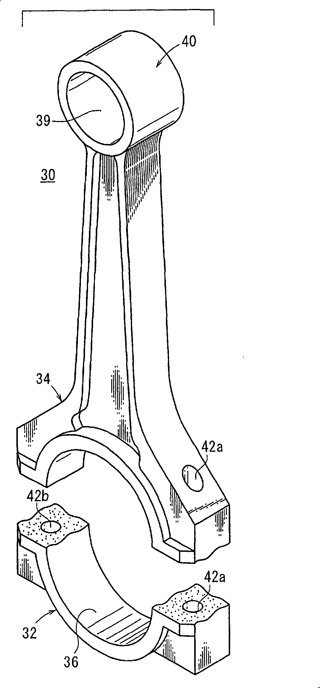
[0068] Figure 1A is a perspective view of a connecting rod 30 as a workpiece to which the present invention can be applied, Figure 1B is a perspective view of the connecting rod 30 which has been split into a cap part 32 and a rod part 34 .

[0069] Such as Figure 1A and Figure 1B As shown, the connecting rod 30 has a large end portion 38 including a cap member 32 and a stem member 34 integrally connected across a generally circular connection hole 36 ; and a small end portion 40 positioned away from the stem member 34 . One end of the large end portion 38 defines a smaller through hole 39 therein. The connecting rod 30 is integrally formed by, for example, casting or forging.

[0070] The large end portion 38 defines a pair of bolt holes 42a, 42b on both sides of the connection hole 36 by a drilling mechanism such as a drill. Bolts 9 a , 9 b described later are respectively screwed into the bolt holes 42 a , 42 b from the cap member 32 side during engine assembly, fo...


PUM


Abstract

A device for manufacturing a connecting rod comprises a fixed stage (62) secured onto a base (60), a movable stage (64) so installed as to be move close to and apart from the fixed stage (62), and a set of backup cylinders (153, 155) displacing the overall movable stage (64) along the axial direction of the connecting rod (30). The set of backup cylinders (153, 155) are substantially simultaneously biased to displace a cap part (32) together with the movable stage (64) until the fractured surface of the cap part (32) of the connecting rod abuts on the fractured surface of the rod part (34) of the connecting rod held on the fixed stage (62). Consequently, the removal and release of chips produced on the mating fractured surfaces can be promoted.

Description

technical field [0001] The present invention relates to a method and apparatus (apparatus) for manufacturing a connecting rod as a vehicle engine component, and more particularly to splitting the large end into a cap part and a small end by integrally forming a connecting rod having a large end and a small end A rod part and a method and apparatus for manufacturing a connecting rod by connecting a cap part and a rod part to each other using a pair of bolts by controlling the tightening force of the bolts. Background technique [0002] A connecting rod connecting a piston pin to a crank pin is widely used in vehicle engines. The connecting rod has a large end connected to the crank pin and a small end connected to the piston pin. In order to manufacture the connecting rod, generally, the large end to the small end of the connecting rod are integrally formed by, for example, forging, and then the large end is split into a cap part and a rod part. [0003] as attached Figure...

Claims


Application Information

Patent Timeline
Patent Type & Authority Applications(China)
IPC IPC(8): B26F3/00B23P13/00F16C7/02
Inventor 奥村秀树小口嗣夫熊谷正男志贺智之桥本祐孝簗田好章
Owner HONDA MOTOR CO LTD
Why Eureka
Try Eureka