Method and device of alignment detection and adjustment of conterminous rotation shafts

A technology of rotating shaft and image detection, applied in the direction of measuring device, optical device, measuring/indicating device, etc., can solve the problems of inconvenient operation, required angle, tangled wire, etc., to achieve the effect of simple and humanized operation

Inactive Publication Date: 2010-06-02
吴士旭
View PDF3 Cites 0 Cited by
  • Summary
  • Abstract
  • Description
  • Claims
  • Application Information

AI Technical Summary

Problems solved by technology

Domestic non-handheld laser alignment instruments generally use the measurement method of the rotating shaft, that is, measure four values ​​of 0°, 90°, 180°, and 270° respectively, and use a personal computer to calculate after recording the values, and then carry out calculations after obtaining the movement of the rotating shaft. For alignment, the laser alignment instrument is only used as an alignment tool, which does not reflect the advantages of high efficiency of the laser alignment instrument
However, the imported laser alignment instrument is expensive, entangled, and has requirements for the angle of the rotation axis of the rotation axis during detection, etc. It is inconvenient to operate.

Method used


Image

  • Method and device of alignment detection and adjustment of conterminous rotation shafts
  • Method and device of alignment detection and adjustment of conterminous rotation shafts
  • Method and device of alignment detection and adjustment of conterminous rotation shafts

Examples


Embodiment Construction

[0025] The content of the present invention will be further described below in conjunction with the accompanying drawings and specific embodiments, so as to facilitate understanding of the content of the present invention.

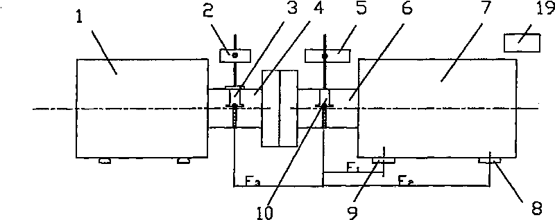
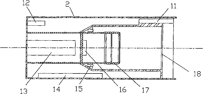
[0026] see figure 1 , figure 2 and image 3 , taking the detection of the rotation center of the rotating shaft of a rotating mechanical device as an example, the mechanical device where the detected rotating shaft is located is divided into a slave device and an active device. It mainly includes the following contents:

[0027] The image detection unit 2 is installed on the active rotation shaft 4 of the active device 1 through the first mechanical installation fixture 3, that is, the deck, the fastening chain and the vertical fixed bracket. The image detection unit 2 is equipped with the first laser emitter 11 and The first inclinometer 12; a group of reflective prisms 21, the integrated laser emission and reflection unit 5 of the second laser emitte...


PUM


Abstract

The invention discloses a method for carrying out centering detection and adjustment of rotating shafts which are connected, and a device thereof. The invention is composed of two sets of mechanical installation chucking appliances, a laser emitting and reflecting unit, an image detecting unit and a data processing and displaying unit. Each of the mechanical installation chucking appliances is composed of a chucking seat, a fastening chain and a vertical type fixed support; the laser emitting and reflecting unit is composed of a semiconductor laser and a group of reflector prisms and inclinometers; the image detecting unit is composed of a fine-resolution camera chain with a high-speed image processor embedded therein, as well as an optical imaging device, an LED backlight, a Bluetooth data wireless transmitting module, a generating laser and an inclinometer which are arranged at the front end thereof; the data processing and displaying unit is composed of a spot center detection and rotating shaft centering adjustment algorithm processing module, a Bluetooth wireless receiving module and a liquid crystal display module. The method and the device have the characteristics of high detection precision and simple operation, and are applicable to the centering detection adjustment of a movable part center in mechanical equipment which is installed horizontally or vertically.

Description

technical field [0001] The invention relates to a method for centering detection and adjustment of the center of mechanical equipment, which is suitable for the centering adjustment of multiple groups of horizontally installed mechanical equipment, especially for two horizontally installed machines connected to each other by couplings or other methods. A method for centering detection and adjustment of the center of rotation of a rotating shaft of a rotating mechanical device. The invention also relates to a device for carrying out the method. Background technique [0002] The centering of mechanical equipment refers to the use of instruments or other testing tools to detect and adjust the relative position accuracy of two connected equipment when installed, or to adjust the centers of multiple sets of movable parts of mechanical equipment to ensure that the centerline lie on the same straight line. Taking large rotating mechanical equipment as an example, if the equipment...

Claims


Application Information

Patent Timeline
Patent Type & Authority Patents(China)
IPC IPC(8): B23Q17/00G01B11/27G05D3/12
Inventor 吴士旭
Owner 吴士旭
Why Eureka
Try Eureka