Experiment test panel for plasma display

A plasma and display technology, applied in the field of experimental test screen for plasma display, can solve the problems of long production cycle and low test efficiency, and achieve the effects of improving test efficiency, shortening development cycle and cost

Inactive Publication Date: 2008-11-19
NANJING HUAXIAN HIGH TECH CO LTD
View PDF0 Cites 4 Cited by
  • Summary
  • Abstract
  • Description
  • Claims
  • Application Information

AI Technical Summary

Problems solved by technology

[0004] The object of the present invention is to propose a kind of unsealed experimental test screen of plasma display used in dynamic vacuum system in view of the shortcomings of long production period and low test efficiency of the existing closed plasma display panel experiment screen

Method used


Image

  • Experiment test panel for plasma display
  • Experiment test panel for plasma display
  • Experiment test panel for plasma display

Examples


Embodiment 1

[0017] like figure 1 , 3 shown.

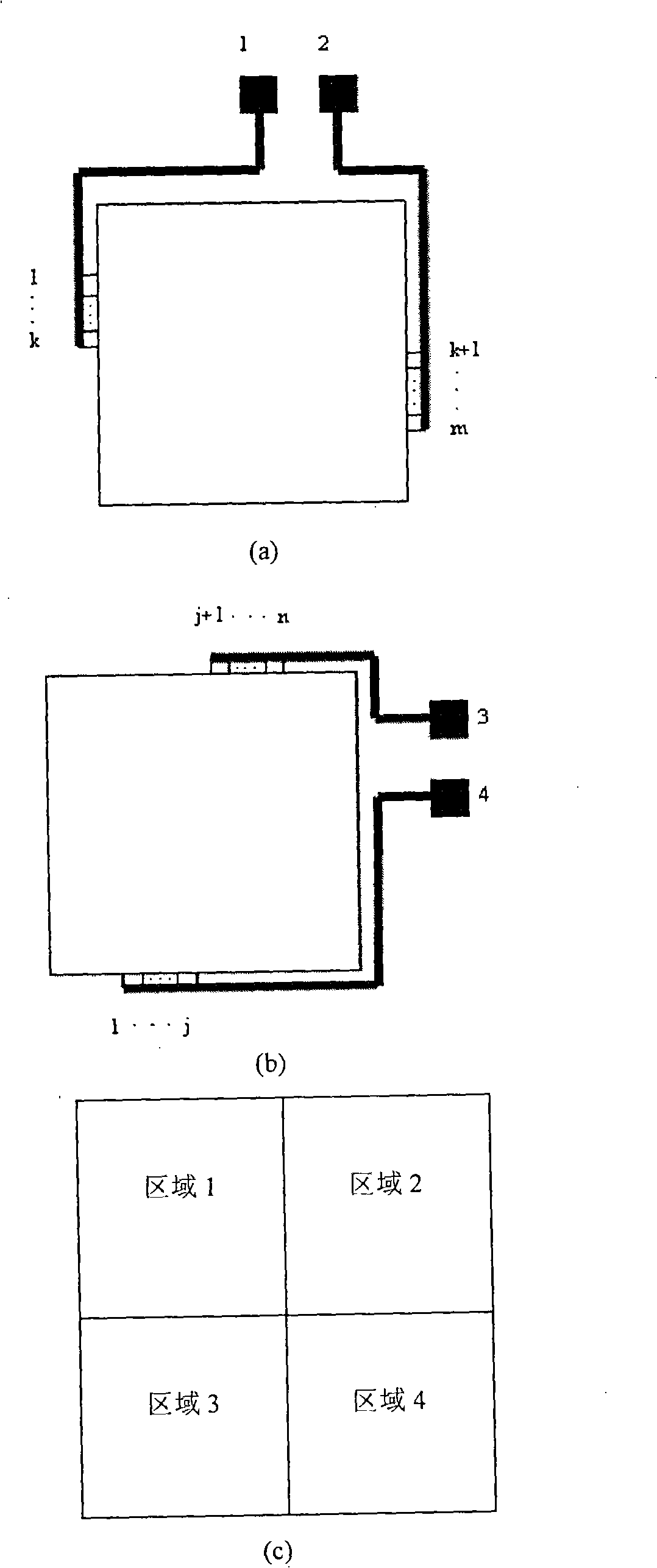
[0018] An experimental test screen for a plasma display, which is composed of a front substrate, a rear substrate and a shadow mask placed in a vacuum chamber, wherein the front substrate, the rear substrate and the shadow mask are not sealed, but are only aligned on all sides, so The rear substrate includes a rear substrate glass substrate, on which a first electrode group is formed, commonly referred to as a column electrode group or an address electrode group, and is formed on a rear substrate glass substrate covering the first electrode group. A dielectric layer, forming a protective film on the surface of the dielectric layer; the front substrate includes a front substrate glass substrate, forming a second electrode group vertically perpendicular to the first electrode group on the rear substrate on the front substrate glass substrate, Usually called row electrode group or scanning electrode group, a dielectric layer is formed on the fr...

Embodiment 2

[0026] like figure 2 , 3 shown.

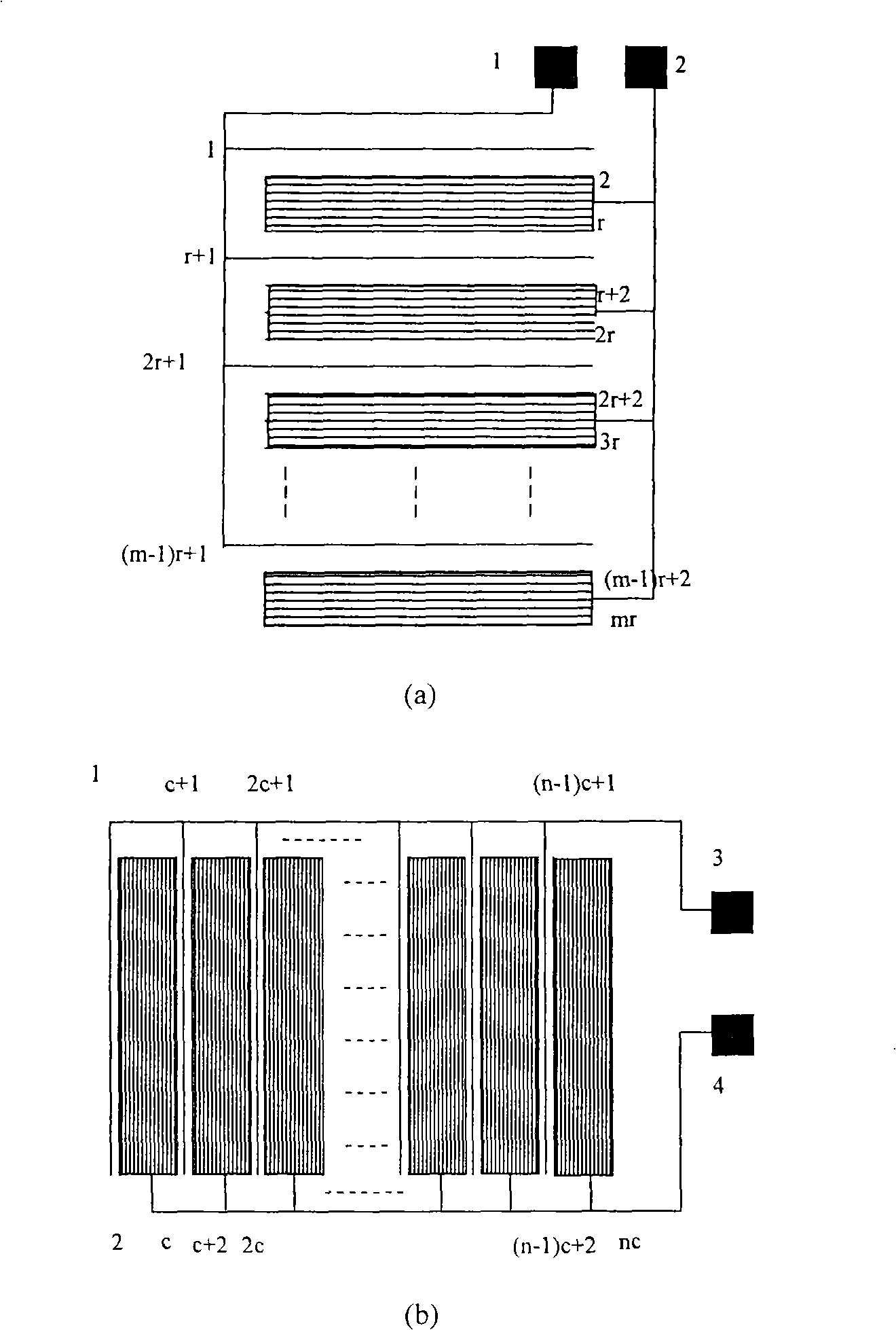
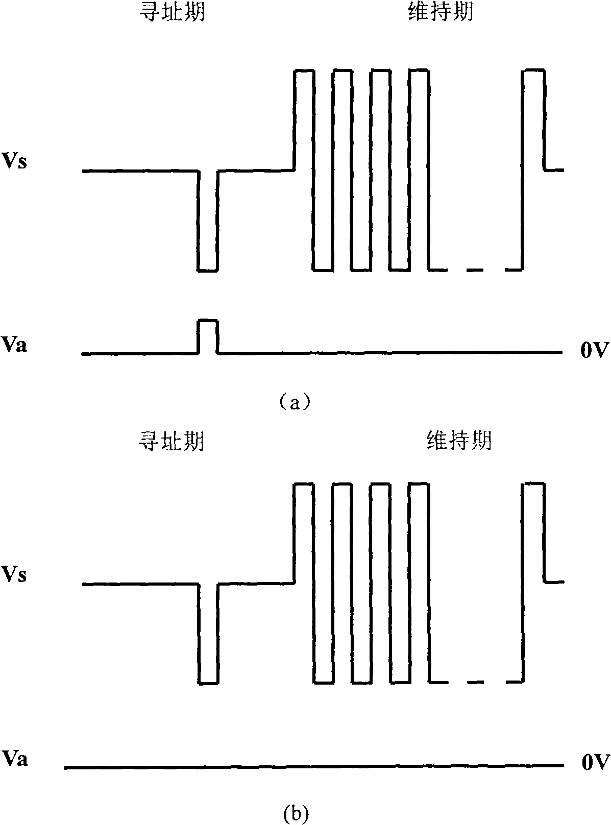
[0027] The difference between this embodiment and the first embodiment lies in the difference in the way the electrodes are drawn out. figure 2 Another connection method of the electrode contacts of the front substrate and the rear substrate of the plasma display experimental test screen is given, figure 2 (a) is a schematic diagram of the electrode contact connection of the front substrate, figure 2 (b) is a schematic diagram of the electrode contact connection on the rear substrate. according to figure 2 Given the way the electrode contacts are connected, in appropriate waveforms (such as image 3 ) driven by figure 2 Full screen display and dot matrix display can be realized.

[0028] For the points that need to be lit, apply negative voltage pulses to the row electrodes during the addressing period, and apply positive data voltages to the column electrodes. The voltage difference between the two exceeds the ignition voltage to...


PUM


Abstract

The invention discloses an experimental testing screen for a plasma display, which is capable of realizing full-screen illumination, partial illumination and single-point illumination in a dynamic vacuum system without sealing the testing screen, aiming at solving the problems of long period, high cost and low efficiency of the test in the current shadow mask plasma displays. The experimental testing screen is characterized in that a plurality of electrode contacts are arranged on the back baseplate and the front baseplate of the testing screen. The electrode contacts are connected with a row electrode group on the front baseplate and a line electrode group on the back baseplate in a definite mode. The working voltage waves generated by a drive circuit are connected to the electrode contacts of the testing screen inside a vacuum cavity through electrode wiring terminals, in this way, external voltage can be applied to the row electrodes and the line electrodes of the elemental discharging unit so that the elemental discharging unit can discharge. The testing screen for the plasma display, which requires no sealing in a dynamic vacuum system, can effectively improve testing efficiency, shorten development and research period and reduce development and research cost.

Description

technical field [0001] The invention relates to an experimental test screen for a plasma display, in particular to an experimental test screen for a shadow-mask type plasma display used in a dynamic vacuum system, specifically an experimental screen that can realize full-screen lighting without sealing the experimental screen. , Partially lit or single-point lit plasma display with experimental test screen. Background technique [0002] The structure of the currently used shadow mask type plasma display mainly includes a front substrate, a rear substrate and a shadow mask. Starting from the glass substrate, the front substrate is the scanning electrode, the dielectric layer, and the protective layer formed on the surface of the dielectric layer; the rear substrate is starting from the glass substrate, and is the addressing electrode perpendicular to the scanning electrode, the dielectric layer, and the protective layer formed on the dielectric layer. The protective layer; t...

Claims


Application Information

Patent Timeline
IPC IPC(8): H01J9/42G01R31/00
Inventor 奚培琳杨兰兰屠彦张雄朱立锋王保平林青园
Owner NANJING HUAXIAN HIGH TECH CO LTD
Why Eureka
Try Eureka