

Optical and electrical combined monitoring apparatus and method in optical transmitting network
A joint monitoring and photoelectric technology, applied in electrical components, transmission systems, electromagnetic wave transmission systems, etc., can solve problems such as high cost, OPM cannot monitor bit error rate, pilot signal transmission performance cannot truly reflect service signal transmission performance, etc. achieve low cost
- Summary
- Abstract
- Description
- Claims
- Application Information
AI Technical Summary
Problems solved by technology
Method used
Image

Examples
Embodiment Construction
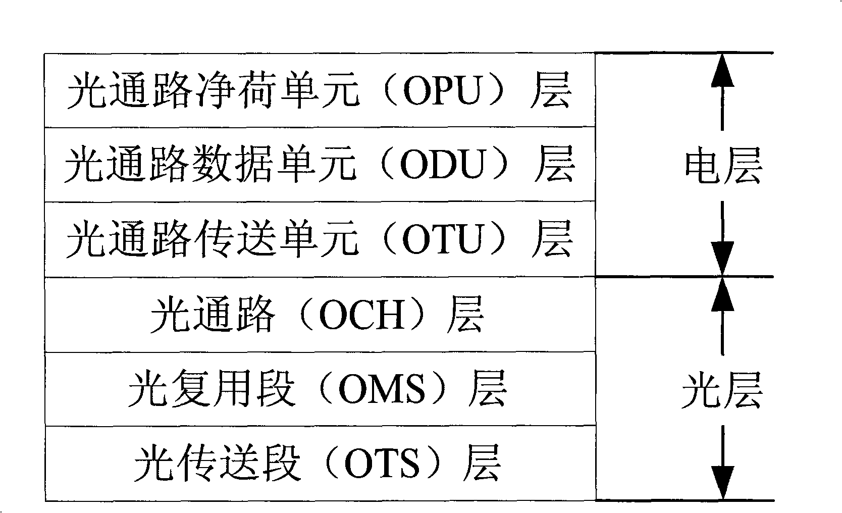
[0033] The present invention improves the original OPM mode and adopts a photoelectric combined monitoring mode. At the optical layer, the OPM function is still used to monitor parameters such as optical power, wavelength, number of wavelengths, and OSNR to realize the monitoring and fault location of various optical devices and optical power. .709 encapsulation format, so the bit error rate and routing information of each channel can be monitored by monitoring the BIP and TTI bytes of the OTU and ODU layers. In order to reduce the cost of electrical layer monitoring, the present invention adopts the method of non-intervention polling monitoring of electrical layer, which is the essence of the present invention. Embodiments of the present invention will be described in detail below in conjunction with the accompanying drawings.
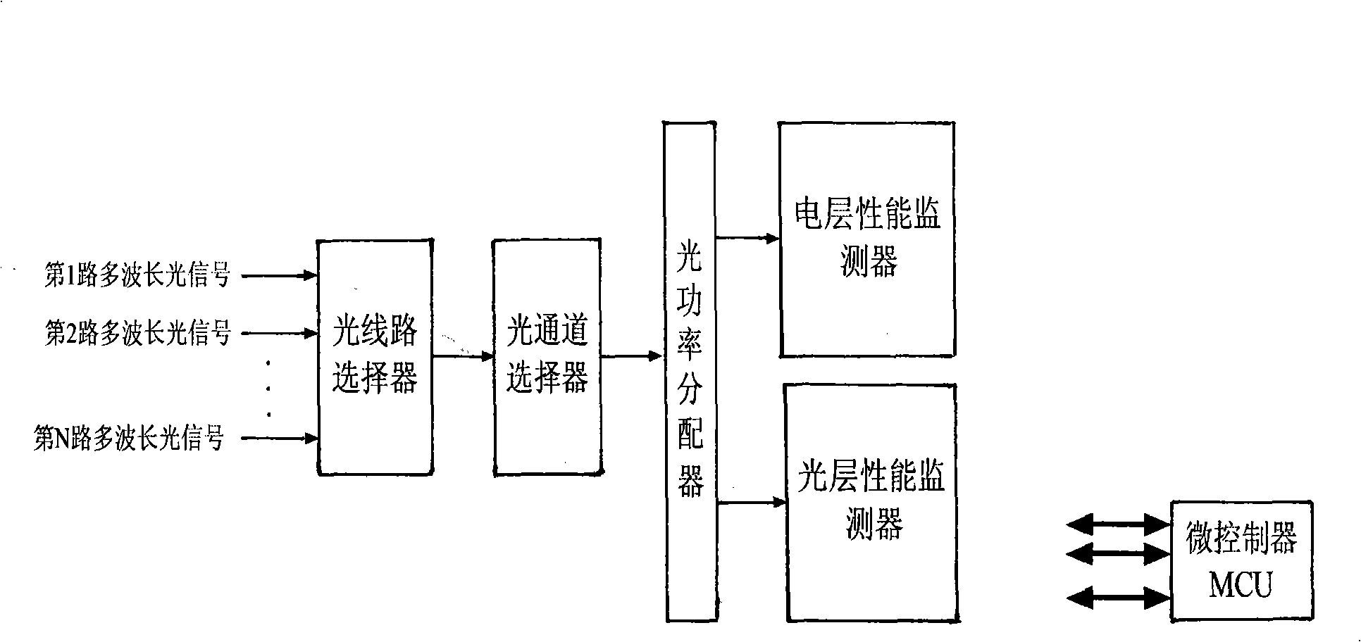
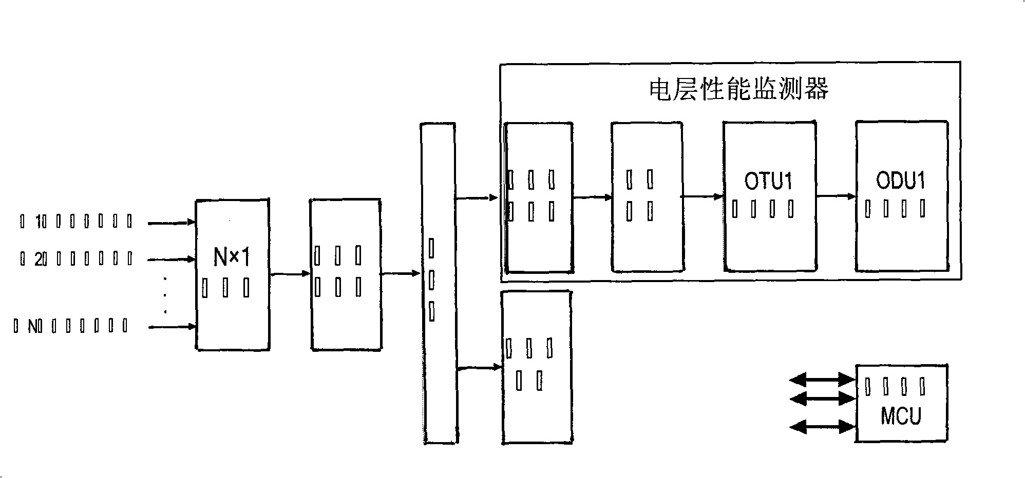
[0034] figure 2Shows the block diagram of the photoelectric joint monitoring device of the present invention, and main unit comprises several such...
PUM
 Abstract
Description
Claims
Application Information