Eureka AIR delivers breakthrough ideas for toughest innovation challenges, trusted by R&D personnel around the world.

Light modulating energy-saving lamp suitable for one-touch control

An energy-saving lamp and key-type technology, which is applied in light sources, electric light sources, lighting devices, etc., can solve the problems of energy-saving lamps such as high cost, complicated control, and inability to replace incandescent lamps generally, and achieve stable light source, cost reduction, and convenient adjustment Effect

Active Publication Date: 2008-11-19
ZHEJIANG YANKON GROUP
View PDF0 Cites 23 Cited by
  • Summary
  • Abstract
  • Description
  • Claims
  • Application Information

AI Technical Summary

Problems solved by technology

Although the above commercially available phase-cutting dimmable energy-saving lamps realize the function of adjusting the brightness of the light source, they all need to design a special dimming device (dimming switch) for the entire control circuit of the energy-saving lamp, and the external dimmer switch needs to be adjusted. The original electrical wiring needs to be modified to meet the needs of the entire control circuit of energy-saving lamps; and there are problems such as complicated control during use and high cost of energy-saving lamps, making this phase-cut dimmable energy-saving lamp still unable to enter the mass market. , still cannot generally replace incandescent lamps

Method used


Image

  • Light modulating energy-saving lamp suitable for one-touch control
  • Light modulating energy-saving lamp suitable for one-touch control
  • Light modulating energy-saving lamp suitable for one-touch control

Examples


Embodiment Construction

[0026] The present invention will be further described in detail below in conjunction with the accompanying drawings and embodiments.

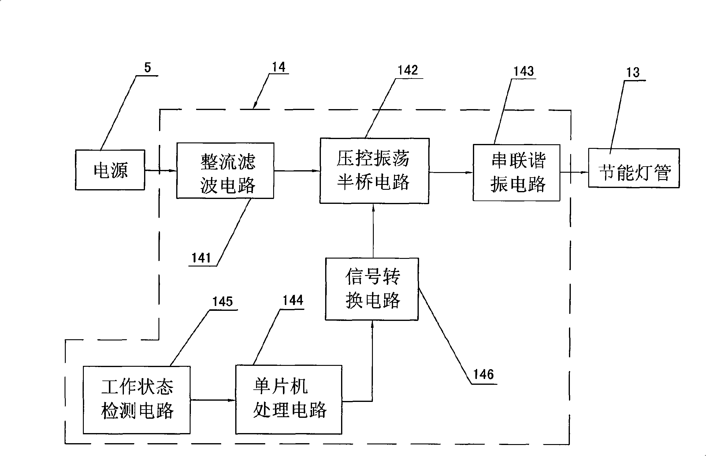
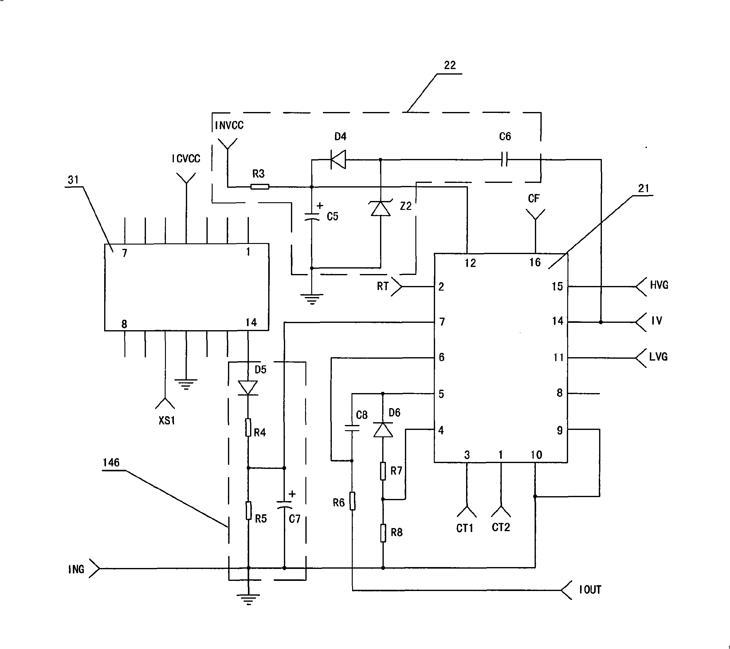
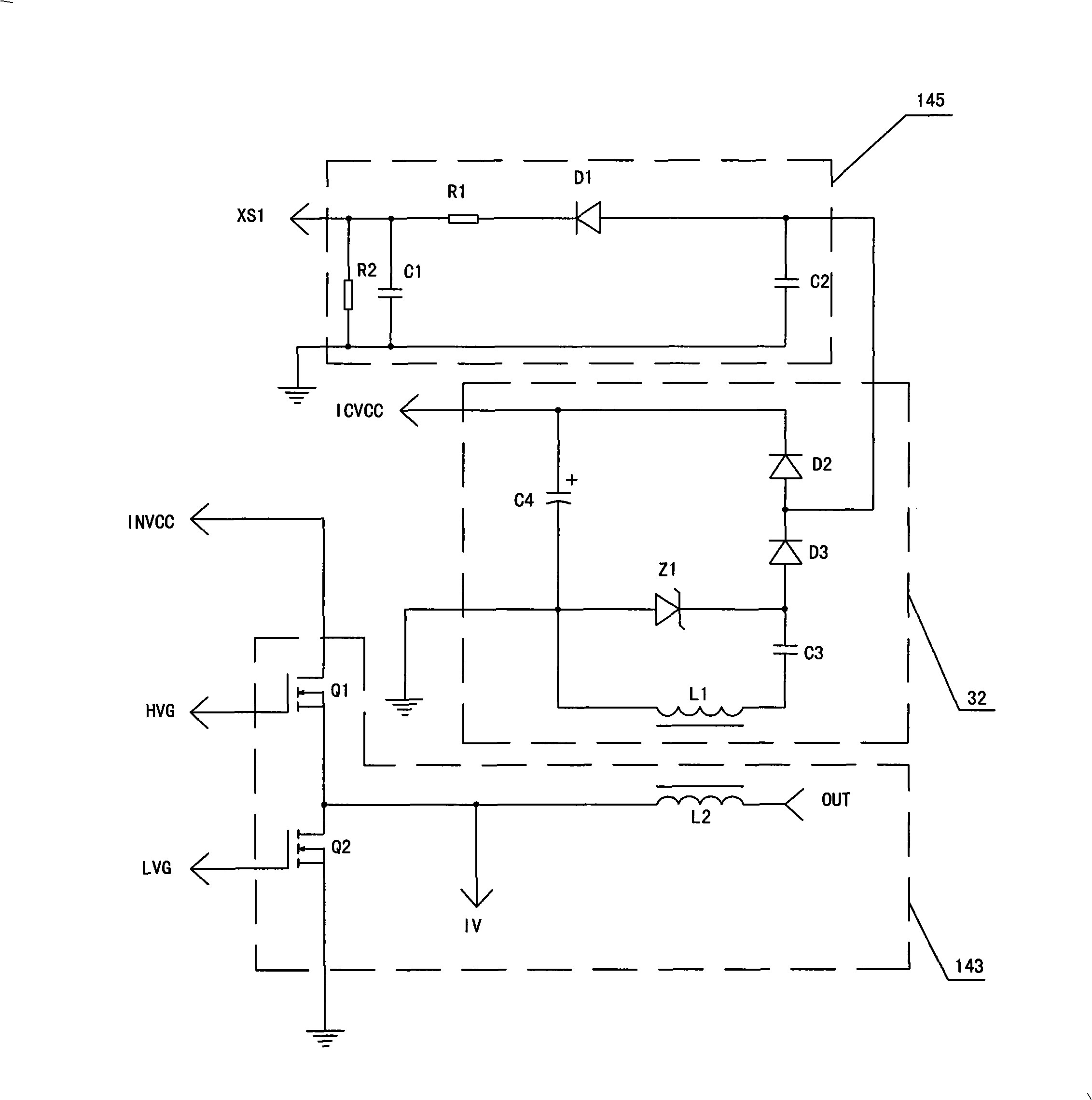
[0027] Such as figure 1 , Figure 2a , Figure 2b and image 3 As shown, a dimming energy-saving lamp suitable for one-button control, the dimming energy-saving lamp 1 includes a lamp base 11, a lamp chamber 12 and an energy-saving lamp tube 13 (light source), and an electronic ballast 14 is arranged in the lamp chamber 12 , the electronic ballast 14 is provided with a rectification filter circuit 141, a voltage-controlled oscillation half-bridge circuit 142 and a series resonant circuit 143, the input end of the rectification filter circuit 141 is connected to the external power supply 5 through the lamp cap 11, and the output end of the rectification filter circuit 141 It is connected with the input terminal of the voltage-controlled oscillatory half-bridge circuit 142, and the output terminal of the voltage-controlled oscillatory half-br...


PUM


Abstract

The invention discloses a dimmable energy saving lamp suitable for one-key type control. which comprises a lamp holder, a lamp cavity provided with an electronic ballast, and an energy-saving lamp tube. A rectifying and filtering circuit, a voltage-controlled oscillation half bridge circuit, a series resonance circuit and a single-chip microcomputer processing circuit are respectively arranged in the electronic ballast, the input terminal of the single-chip microcomputer processing circuit is connected with a working state detecting circuit, and the output terminal of the single-chip microcomputer processing circuit is connected with the voltage-controlled oscillation half bridge circuit through a signal converting circuit; the dimmable energy-saving lamp has the advantages that when the working state detecting circuit detects that the on / off state of the power switch is changed, then different PWM signals can be outputted by the single-chip microcomputer and are converted into average voltage, the average voltage is inputted to the input terminal of the voltage-controlled oscillation half bridge circuit after being fitted, to ensure that the working frequency of the electronic ballast and the light source current can be changed according to the controlled requirements, and thereby the purpose that the brightness of the light source can be adjusted can be realized; the adjustment to the brightness of the light source can be realized through the on / off conversion of the power switch in the dimmable energy-saving lamp, a dimmer switch is eliminated, and the original electrical wiring is not required to be modified during the process of installation.

Description

technical field [0001] The invention relates to a lighting device, in particular to a dimming energy-saving lamp suitable for one-button control. Background technique [0002] my country has a large population and relatively poor per capita resources. Using energy-saving lamps to replace incandescent lighting has far-reaching significance for saving the country's precious electric energy. However, due to many factors, the current energy-saving lamps cannot completely replace incandescent lamps as the main lighting tool. One of the troublesome factors is: under normal circumstances, the existing energy-saving lamps cannot adjust the brightness of the light source. ——Thyristor AC voltage regulator forcibly dims the existing energy-saving lamps, then the energy-saving lamps will not work normally, and the energy-saving lamps will appear obvious flickering phenomenon, which will not be able to play the lighting effect, and will also greatly reduce the energy-saving lamps. The s...

Claims


Application Information

Patent Timeline
Patent Type & Authority Applications(China)
IPC IPC(8): H05B41/392
Inventor 陈以平钱建平
Owner ZHEJIANG YANKON GROUP
Why Eureka
Eureka Blog
Learn More