Method and apparatus in connection with laser use

A laser, laser source technology, applied in laser welding equipment, welding equipment, manufacturing tools, etc., can solve the problems of uneven intensity distribution in the processing direction, changing the nature of the problem, and unsuccessful provision, etc., to achieve excellent surface finishing and cleaning Processing, easy-to-control effects

Inactive Publication Date: 2008-11-19
LASER LANE OY
View PDF3 Cites 12 Cited by
  • Summary
  • Abstract
  • Description
  • Claims
  • Application Information

AI Technical Summary

Problems solved by technology

Therefore, the solution in question does not actually achieve sufficient functionality, since the end result in terms of processing quality depends, for example, on the processing direction (homogeneous / non-uniform intensity distribution)
Therefore, the solution in question does not succeed in providing a decisive improvement in terms of eliminating the "shadow" problem, since it merely changes the nature of the problem

Method used


Image

  • Method and apparatus in connection with laser use
  • Method and apparatus in connection with laser use
  • Method and apparatus in connection with laser use

Examples


Embodiment Construction

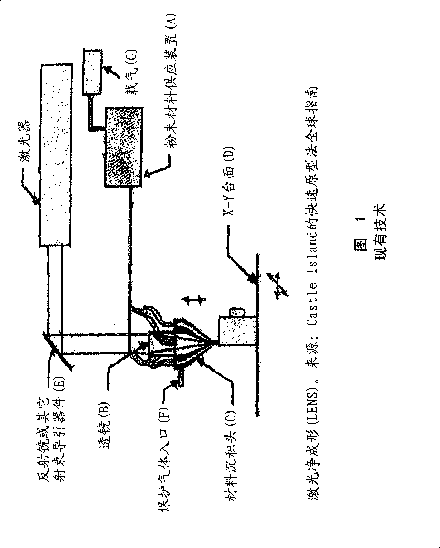
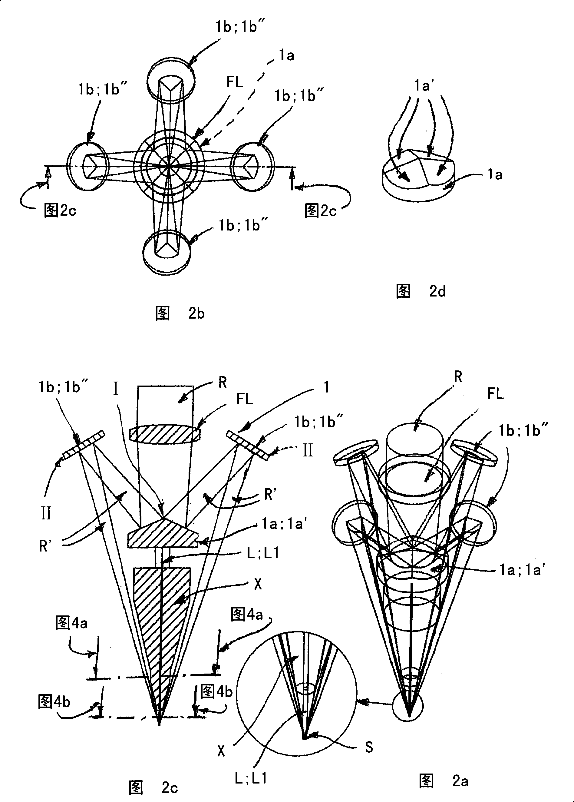
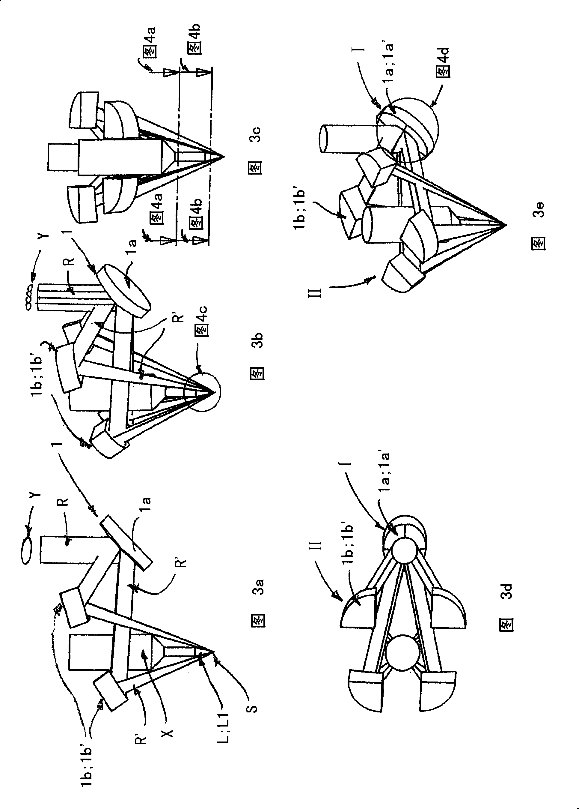
[0020] The invention relates to a method in connection with the use of lasers, in which one or more laser beams R emitted by one or more laser sources Y are focused on the fusion site S by means of a beam-guiding element 1, at At the fusion point, the filler material L supplied to the fusion point is melted and thus used in particular to carry out welding, coating, component manufacturing and / or similar processes. The filler employed comprises substantially solid elongated filler material L; L1, such as welding wire or similar material, which is passed through a delivery system X relative to a single strand focused on the fusion site as shown in Figure 3a. A laser beam or a plurality of laser beams focused on the fusion site as shown in FIG. 3 b is supplied to the fusion site S in a central manner. The divergence I of one or more laser beams R is produced by the multi-segment mirror 1a, in particular to maintain the symmetry of the intensity distribution of said laser beams, w...


PUM


Abstract

A method in connection with laser use, wherein one or more laser beams (R) emitted by one or more laser sources (Y) are focused by means of beam guiding elements (1) on a fusing spot (S) , whereat a filler (L) delivered thereto is melted, especially for performing a welding, coating, piece manufacturing and/or the like process, the employed filler comprising a substantially solid-state, elongated filler material (L; L1) , such as a wire or the like, which is fed by means of a delivery system (X) to the fusing spot (S) centrally relative to said one or more laser beams (R) focusing on the fusing spot (S) . The one or more laser beams (R) are diverged (I) with a multi-segment mirror (1a) , especially for maintaining the symmetry of the intensity distribution thereof, whereby beams or divisional beams (R' ) , reflecting from its various segment elements (1a') in substantially divergent directions, are converged (II) on the fusing spot (S) by means of a condenser system (1b) included in the beam guiding elements (1) .

Description

technical field [0001] The invention relates to a method related to the use of lasers, in which one or more laser beams emitted by one or more laser sources are focused on a fusing spot by means of a beam guiding element, at At the fusion point, the filler material delivered to the fusion point is melted and thus used in particular to carry out welding, coating, component manufacturing and / or similar processes. The filler employed comprises substantially solid elongate filler material, such as welding wire or the like, which is passed through a delivery system so as to be centrally located relative to the one or more laser beams focused on the fusion site way is supplied to the fusion site. Background technique [0002] For example, LENS (Laser Engineered Net Shaping) rapid manufacturing technology (RP, rapid prototyping method), such as shown in Figure 1, utilizes a single laser beam that is optically centered is focused on a focal point to create a fused site on the subs...

Claims


Application Information

Patent Timeline
Patent Type & Authority Applications(China)
IPC IPC(8): B23K26/067B23KB23K26/06B23K26/34
CPCB23K35/0244B23K26/34B23K26/0608B23K26/0604B23K35/0261B23K26/067C23C26/02
Inventor K·艾托V·-P·英莫南
Owner LASER LANE OY
Why Eureka
Try Eureka