
Reflection imaging system

An imaging system, specular reflection technology

Inactive Publication Date: 2008-11-26
CONSERVE & ASSOCS
View PDF0 Cites 8 Cited by
  • Summary
  • Abstract
  • Description
  • Claims
  • Application Information

AI Technical Summary

Problems solved by technology

[0004] The head-up display originated from aviation technology, and the known aviation head-up display is very complicated in structure, bulky, and the setting position and magnification are fixed, cannot be adjusted, and the price is quite expensive
[0005] With the advancement of technology, head-up displays have gradually become popular in automotive applications, but the known head-up displays for cars use direct-view displays as image sources, and the brightness is low

Method used


Image

  • Reflection imaging system
  • Reflection imaging system
  • Reflection imaging system

Examples


Embodiment Construction

[0038] The detailed description is as follows, and the preferred embodiments are only for illustration but not for limiting the present invention.

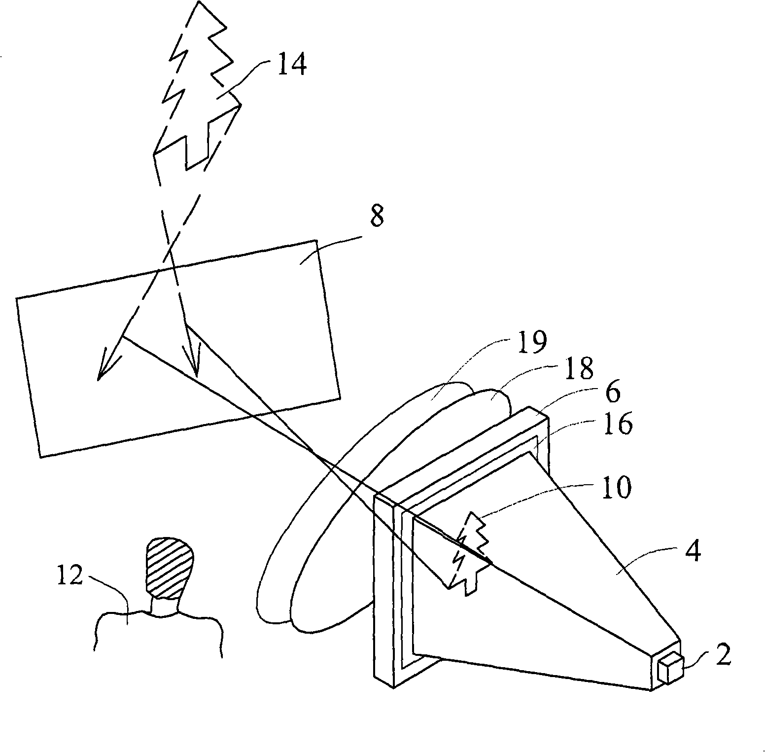
[0039] figure 1 It is an application diagram of a reflective imaging system according to an embodiment of the present invention. The reflective imaging system includes: a light source 2; a light pipe 4; an image panel 6; and a surface 8 having at least partial specular reflection properties. The light emitted by the light source 2 is irradiated to the image panel 6 through the light guide 4, and an image 10 on the image panel 6 is projected onto the surface 8, and then reflected to a viewer 12 to form a virtual image (virtual image) that the viewer 12 can see. )14.

[0040] In one embodiment, the image 10 and the virtual image 14 can be black and white, monochrome, multi-color or full-color.

[0041] In one embodiment, the light source 2 can be a light emitting diode (Light Emitting Diode, LED), a laser diode (Laser Diode, LD), ...


PUM


Abstract

The invention relates to a catoptric imaging system that comprises at least one light source, at least one light pipe arranged in front of the light source, an image panel arranged in front of the light pipe and a surface provided with at least the partial reflection characteristics of a mirror face. Light from the light source is irradiated to the image panel by the light pipe and an image on the image panel is projected to the surface to be reflected on a looker-on, thus forming a virtual image that can be seen by the looker-on. Owning to the light pipe of the invention, an incident light from the light source is reflected on the image panel with less light loss and higher directivity, so the looker-on can see the image with higher brightness. In addition, owning to the light pipe of the invention, the incident light from the light source can be irradiated to the image panel evenly, so the looker-on can see the image with uniform brightness and better quality.

Description

technical field [0001] The present invention relates to an imaging system, in particular to a reflection imaging system. Background technique [0002] Traditionally, projectors are often used in conferences, business presentations and educational training. In recent years, the technology of imaging modules and displays has advanced by leaps and bounds, such as liquid crystal display projectors, digital light processing projectors (Digital Light Processing, DLP) or liquid crystal on silicon projectors (Liquid Crystal on Silicon, LCOS), etc., so the combination of imaging Module and display products are gradually applied in various fields, such as home theater, helmet mounted display, small portable display and head-up display (HUD). [0003] Known projection displays are usually projected on reflective surfaces or screens with diffuse reflection properties, so their applications are limited. [0004] The head-up display originated from aviation technology, and the known avi...

Claims


Application Information

Patent Timeline
Patent Type & Authority Applications(China)
IPC IPC(8): G02B17/06G02B6/00G02B1/00G02B1/10
Inventor 陈政寰
Owner CONSERVE & ASSOCS
Learn More